• Please only use these forums for blogs, they are not a discussion forum

PollyMobiles Rebuild

so researching into the available IR thermometers my findings are:

the traditional handheld thermometer gun:
too expensive
screen and circuit are way too long n bulky to group together

flir.JPG


ear thermometer:
way too expensive
only measures 30-50C
circuit again prob too bulky to bunch up

ear.JPG


these £5 cheapo IR thermometer from china:
cheap n compact but very slow delivery till next month

IR.jpg


so went to maplin and they sell a tiny pen pocket IR thermometer for £15
http://www.maplin.co.uk/pen-type-pocket-infrared-thermometer-626124?c=maplin&utm_source=gcs&utm_medium=gcs_search&utm_campaign=N78LL&utm_content=Enviroment Testers

price is abit high since i need 3 per tyre (£15 x 12 = £180 total) woulda preferred the cheap ones (£5 x 12 = £60)
display is small and just shows the value, exactly what i want.
u have to push & release the button for a sec to boot it up before u can hold it down for a constant reading.
I'd prefer if it was a simple press n hold to immediately take constant readings like on most IR gun.
testing against my IR gun its reading bout -2C off.

DSC07752.JPG


thin compact circuitry. all the multiple units will be connected to the same power supply

DSC07751.JPG


the display is delicate so I'd need to build some secure framing case to hold it tight against the circuits. the trigger buttons from multiple units will prob be gathered into a single toggle switch.

DSC07750.JPG


IR sensor only has 2 pins which is good. so I'll desolder and extend it to mount in the wheel arch

DSC07754.JPG


the wasted rear half of the circuit is mainly for the battery so I could cut it off to reduce size n bunch up the displays
 
Last edited:
on closer look the IR sensor is actually 4-pins

DSC07753.JPG


two at top

DSC07754.JPG


two underneath

DSC07755.JPG


trying to desolder the sensor off, damn its so fiddly. my desolderer is way too violent, almost knocks the fragile display apart so had to tape it down. ended up carefully bending the pins inwards to clear the track n pry the solder apart with a blade. I hope the heat hasn't damaged the tiny sensor

DSC07756.JPG


desoldered the sensor and switches

DSC07757.JPG


now i just realised the scale of the task. each sensor has 4 terminals, each of the 4 tyres have 3 sensors, so each cable from a tyre needs 12 wires, a total of 48 channels to solder up :/

only cable that has that many wires is an old printer parallel cable

DSC07758.JPG


it has least 19 channels

DSC07759.JPG


but i only have two 2.5m lengths, not long enough, although they cost pennies on ebay :)

DSC07760.JPG


good idea to start allocating each wire per terminal for each cable. R- identified by the non-black pin.

DSC07762.JPG


before committing to buying 11 more £15 thermometers, i should test the extended sensor and see if the added resistance will affect the reading alot
 
Last edited:
About the resitance effect I think it will depends on the cable/wires quality and your solder quality, try to go for the less tin you can. An alternative could be a shielded RJ45 cat5; very weak resistance until 100M but they got only 8wires.
 
cheers seb

bloomin heck its so difficult soldering at this small scale and noticed my hands r not as steady as used to be

DSC07763.JPG


wired up a bi-stable switch so you just plug in the power, touch the button once and its always on

DSC07764.JPG


and the result is mixed.

yes the sensor reads roughly the same -1C offset as before (if my warm fingers handle it by bout 5cm away from the sensor), so the 2.5m cable doesn't affect it much,

BUT the temperature of the sensor itself relative to the object really affects it alot
(ie. blowing onto or even holding the wiring near the sensor would change its temp so the reading goes haywire)
(so the breeze through the wheel arch will affect the sensor)

plus the 1:1 distance:area reading makes it really inconsistant

DSC07765.JPG


so given the difficulty and inconsistancy I may have to rethink this, ah well
 
Last edited:
cheers ed, yea i spotted that low-cost iphone thermal cam mod. only need to measure 3 spots and don't have or afford 4 iphones/ipods

the point is i wanna monitor & record the inner/mid/outer temps of each tyre while it's loaded on track to aid in refining tyre pressure and alignment/camber.
the outer front tread tended to overheat n tear off cos I had unsufficient camber so being able to measure the heat across the tread at that point of the track could help me tune the amount of camber.
 
You only need to buy a bunch of sensors then write some code to read each one in turn and data log it. You dont need to spend on loads of hardware you don't need if you did it this way. Is there a part number on the sensor?
 
indeed a sort of data logger for the IR sensors woulda been my ideal choice but I have no idea how to go bout connecting external I/O to my laptop nor write a script to interpret & log that data, hence videoing a bunch of existing thermometers was the only way I know.

I do abit of basic java/c++ at work as a game developer but that's mainly towards basic game parameters.
would be gr8 if I knew what I/O hardware I need and the parameters of how to communicate with em. shall google it.

the tiny maplin pen thermometer sensor didn't have any marking but the larger normal thermo gun did say heimann 3849 148
 
a quick google bout diy logging infrared thermometers led me to afew instructables n articles bout programming an Arduino to record the IR sensor or how to make a thermal coloured flashlight etc
all this computer science stuff is new n baffling to me but boy its like playing with toys of infinite possibilities :)

anyway shall carry on researching into a multi IR temperature data logger so I could playback the temp values overlayed the onboard videos.
this could get complicated for me
 
k after a rethink, may have to give the onboard IR data logging a miss cos:
1. there's no place to effectively secure the sensors all pointing at the tyre
2. all the wheel arch wind n debris will affect each sensors accuracy
3. extending a bunch of cheap miniature ready-made IR thermometers = £60 total but difficult soldering & inaccurate
4. building own logger from scratch = £144 for 12 IR sensors + £10-20 arduino pcb but have to write program and could still be inaccurate

so maybe probe deep inside the tyres after each run instead?
a tyre probe has a thin needle thermometer but cost £35 plus the reading pyrometer itself for £85 = £120 eek
a meat probe is alot cheaper but the tip is prob too thick to penetrate the rubber

or easiest cheapest way is to just use my current IR thermometer gun to measure the vague tread surface temp after each run and try get it roughly even. yeah think that'll do for me
 
hmm the rear end of the coilovers have tended to be quite stiff as complained by previous rear passengers.
used to think the rear spring was too hard for the light rear but i think it's actually due to the very short rear bump travel (front has 40mm bump while the rear has only 20mm bump travel) due to the exhaust in the way, so it often hits the bumpstops when loaded up over rough roads, increasing the springrate, transferring more force and jolting the back passengers.

so rerouting my backbox pipes to clear the suspension more is prob another thing to add to this years to-do list. so then i could readjust the rear susp with 33mm bump travel
 
Cant really see the point to the above, but this project would help you a lot:

http://www.kickstarter.com/projects/andyrawson/ir-blue-thermal-imaging-smartphone-accessory?ref=card

hmm i maybe tempted now by IRblue if it's available cos:
- it'll give a better definition of the actual tyre temp distribution (can identify the hotter tread area)
- the whole IR array n circuits encased so less affected by wind n debris n more accurate n consistant
- i could get 3 more cheap old used ipod touches from £30+
- seems to connect via bluetooth and has its own battery source so alot easier to install (no more wires!)
 
Seriously, just use a physical tyre temp sensor, if its good enough for race teams, its good enough for you :)
 
most meat probes have a thick tip of least 4mm which won't penetrate rubber without difficulty or damage but then I found this device with a thin 1.7mm needle probe and big readout screen and suitable working spec which may do the job :)

11063_F_WEB_13J1.jpg


http://www.deltatrak.com/index.php?11063-jumbo-display-auto-cal-needle-probe-thermometer

available on ebay from usa for bout £23.05 + import
http://www.ebay.co.uk/itm/DeltaTRAK-Jumbo-Display-Flash-Check-Needle-Probe-Thermometer-Model-11063-/121025346710#vi-content

will obviously need to adapt an adjustable depth stop to it (measure tread depth and set probe tip to same depth) so i don't accidentally puncture the tyre
 
Last edited:
now that the seasons warmed up slightly, i wanna retweak the map cos she seems to occasionally lean to 15-16afr when cruising at 70 (3-4k rpm / 25-30% load regions of the fuel map)

so this was the map i ran back in august 2012 during JAE with O2 disconnected, multiplier 300 and latency 240

auga.jpg


tday i had to lean the mulitplier to 292 so the cruising and boost afr are correct but that mid-region (just below 0psi at 3k 70mph) still leans out to 16afr so had to richen that area slightly to get back to low 14afr. idle cells leaned abit more to idle at 14.7afr

januq.jpg


curiously i tried out the original turbo remap that Ed dyno tuned for me back in sept 2011 and the mixture on that no longer works cos it used to rely on the O2 to correct the low-load regions.
now without the O2 it idles 10afr, cruises at 11-12afr but boosts at 10-11afr.

after a cruise i measured the tyres with my IR gun as a rough test and both the fronts are 18,16,16C in,mid,outer and both rears are 14,14,14C. front & rear warm pressures at 3bar which seems bout right for normal driving.

another note is I believe the LSD isn't working again. exiting t-junctions it wheel spins very easily like an open diff and on/off power mid-turn no longer load/unloads the steering anymore.

when both wheels jacked up, they both turn the same way so there's some preload there.
but when only one wheels up and i spin the wheel to check amount of preload, there's minimal resistance.

so either the lsd plates are worn thin and/or the preload ring was too weak.
this gripper lsd not turning out to be very reliable or easy to setup

next time I take the LSD apart, rather than sending it off to gripper to be ripped off labour, i think I'll just fit a thin spacer washer between the preload ring and the casing to squeeze the clutch pack slightly more = more preload
 
speaking of lasers, I may also be looking at making my own diy laser guided alignment rig so when I've adjusted the camber on track I can quickly correct the toe alignment.

another note bout droop limiters I mentioned back in post 3525:
rather than welding some hooks etc onto the expensive alloy coilover hubs to attach straps onto like ebbdude,
instead I'm thinking of making a reinforced coilover cover (like what's fitted at the moment but made out of the same strong fabric as the straps) which are of specific length (hence limit droop) and wrapped/anchored (with cable or jubilee clip) one end at the top of the front strut/top of rear damper and the bottom of the front strut preload ring/rear damper base.
will include diagram later of course.
 
was gonna buy some £10 laser pointer n make my own laser jig but looking around the garage i found i had a laser spirit level, brill :)

DSC07766.JPG


now I know the laser light is straight but whether it is aligned parallel to the base of the level requires calibrating.

to find out we need to place the spirit level on a completely flat surface, measure & compare the "surface to laser dot distance" at the emitter and on the projected wall far away.

i don't have any flat surface long enough.
there's only two things i know that are flat at long distances:
- a calm water surface (impractical, messy, don't have a big bath and can't rest the spirit level on it)
- and a laser light

i do have a flat counter-top and a far wall so i could use my laser pointer to set the reference plane of that surface onto the wall.

position the emitter port at the edge of the table n pointed slightly up

1.jpg


as you slowly swivel the pointer down, the projected dot gets lower until its parallel to the surface and the projected dot can't fall any lower, thats the reference plane of the table top. mark it on the far wall

2.jpg


if we angle the pointer any lower, the beam starts to reflect off the surface and the dot begins to rise from its lowest point

3.jpg


now we place the spirit level on the flat surface then measure & compare the "reference plane to laser dot distance" at the emitter and on the projected wall far away.
mine was pointing slightly down

4.jpg


to level the beam i placed a sheet of folded twice paper under the front of the spirit level, remeasured and yay it matches

5.jpg


now with the laser corrected by the thin folded paper, I made the jigs by cutting 415mm lengths of the same thickness wood so they sit on the edge of the alloy rims.

tape the level onto one of the jigs.
add up the "base to laser dot distance", offset distance between front/rear wheels and thats how far away the laser should be pointing from the outer face of the rear jig (notice the taped ruler)

DSC07767.JPG


laser jig tied to the front alloy

DSC07768.JPG


rear measuring jig tied to the rear alloy

DSC07769.JPG


surprised it's so sensitive to the most minute steering movement, even with the steering lock engaged

the flexible tyre gripping onto the floor will influence where the steering alignment "flexes back to" after any adjustment so to eliminate that flex, I'll need to make a bearing turn-table so the wheel can swivel effortlessly

also the steering wheel moves about quite alot even with steering lock so i'll have to tie a rope to pull the steering to one side up against the lock to keep it still
 
Last edited:
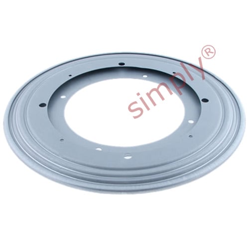
Aha whilst searching for roller thrust bearings i've just found out that what i actually needed to put under the wheel is called a "lazy susan turntable" usually used in cake making and in chinese restaurant centre turntables plus they're cheapas chips :)
 
A cheap option i used to get mine roughly right Paul, two biscuit tin lids ontop of each other with a squirt of oil in between them lol ;) good for bleeding the powersteering as well (when it was fitted)

Keep up the good work!
 
Indeed I've read of using grease between 2 sheets of metal/plastic, bin liners and I used to use 2 floor tiles with salt inbetween.

But i'm after a completely bindless pivot and a lazy susan seems to be the ideal cost effective solution without the £200 tag of a proper turntable
 
brought another £10 laser level from toolstation for the other side.
nice that it features an adjustable rear ramp if the laser was pointing too far up

DSC07770.JPG


but the laser emitter can be fine-tuned with these screws too

DSC07771.JPG


calibrate both the laser levels next time before fitting on the jigs
 
Last edited:
the new laser level also points downward too.

adjusting the beam with folded paper seemed quite inconvenient and inconsistant so I drilled a screw hole under the front of the level so after ducktaping the spirit level onto the wood, i tighten the screw which finely pushes the front end up against the elastic tape until the beam measures level

DSC07772.JPG


both beams calibrated

DSC07773.JPG
DSC07774.JPG


just need to make the lazy susan plates, setup a level platform for the car to sit flat on (using the water level in flexible tube trick) and we're ready to align
 
Last edited:
well tday the lazy susan bearings arrived, only ordered it yesterday :)

DSC07775.JPG
DSC07776.JPG
DSC07777.JPG


unexpectedly i got another package and its a k11 thrust bearing? I didn't order it. last time i ordered one seperately was for the 200mm helix clutch last year. maybe someone resent a completed order by mistake? better not have charged me, gotta check me card balance

DSC07779.JPG


in me bedroom I actually had this thick counter-top wood, perfect for supporting the wheels n keeping the lazy susan flat

DSC07778.JPG


since the surface is much smoother n harder than the current rough planks I used on the jig, may as we remake em

DSC07780.JPG
DSC07793.JPG


cut the big 3mm thick hardwood into 23x23cm tiles for levelling the platform height under each wheel

DSC07784.JPG


cut 23x23cm squares from the counter-top wood

DSC07781.JPG


just big enough to hold the lazy susan

DSC07782.JPG


marked n drilled the mounting holes

DSC07786.JPG
DSC07787.JPG


Mmm i luv precision

DSC07788.JPG


screw on the other plate through this inspection hole

DSC07789.JPG
DSC07791.JPG


2 lasy susan turntables

DSC07792.JPG


k place em under the wheels and although the bearing provides a low friction plate (any steering movement = tyre immediately follows without any stuttering) I noticed that unless the bearing axis was exactly in-line with the steering axis, the steering would just bind up or "spring" back from the tyre flex. grrr

tried shifting it in all sorts positions to find the steering axis where it won't try to slip or shift the body but was near impossible, like there's no single static steering axis. I did find through some testing that the castor trail is bout 15mm ahead of the hub axis

DSC07794.JPG


tried the greased plates, shopping bag and this tough rice bag below was the most slippery.
they're all fine for large fast steering movement but during slow movements, such as fine adjusting the trackrod ends, they tend to stutter n grab too much so the steering movement feels too elastic as the tyrewall flexes between each stutter

DSC07795.JPG


so the round "grooved" bearings provide smooth friction-less movement but the axis is too restrictive causing geometry binding.

while the slippery plate/bags provide unidirectional movement but to much friction.

what I need then is a unidirectional bearing plate (both rotates & slides laterally) like a bunch of ball bearings unrestrained between two flat plates. dunno if u can buy one so I'll make one instead, can't be that hard
 
Last edited:
k just designed one like this

circular array of balls in a round plate (to both rotate and slide freely) with raised edge shoulder to stop it before the plate or balls slip over

unidirect plate 1a.jpg


balls will need this retainer to keep em together or else they'll just roll about n jam the plate movement

unidirect plate 1d.jpg


cut-away of the assembly

unidirect plate 1e.jpg


when the plates slide over to their edge

unidirect plate 1f.jpg
 
Last edited:
updated the design this morning with more range of angle

unidirect plate 3.jpg


here's a sim of turning the plate upto 100deg if the steering axis was near the inner tread

platform1.gif


if the steering axis was along the inner tread but ahead of the contact patch (most likely due top castor) then it turns like this

platform2.gif
 
Last edited:
rather than cut new wood n waste material, I'll reuse the prev thick square panels.
countersunk the screws to plug up the holes n make the surface flat

DSC07796.JPG


found I had a bunch of 11mm glass marbles, use them as bearings.
cut a 10x10cm bearing retainer out of 10mm thick board

DSC07798.JPG


drill a 10mm hole first and then use a 13mm countersunk bit to enlarge the holes but just before reaching the end of the 10mm hole. this creates a retaining lip so the 11mm marble can't fall through

DSC07799.JPG


marble sits nice n centre

DSC07800.JPG


finished bearing

DSC07801.JPG


place in middle of plate. the wooden retainer just rests on the surface and stops the balls rolling off

DSC07802.JPG


placed under one wheel. wedged against the wall to prevent the front rolling off when i jack up the other side

DSC07803.JPG


first issue is the 4 balls are concentrating the 300kg corner weight (75kg each ball) onto the soft wood surface and denting it so it jams. need a harder surface

DSC07804.JPG


so shuved smooth floor tiles against the marbles and yay it works. smooth turning, no stuttering. very slight springiness at high steering angles due to the wheel camber tilting from the castor and compressing one side of the tire.

DSC07805.JPG

DSC07806.JPG


so tdays test result is:
  • need more balls across the surface to spread the load (got loads of em)
  • balls have to roll on a smooth hard surface preferably sheet metal cos ceramic can chip off
  • figured I don't need to limit the size of the bearing retainer plate (previously thought the balls would drop out if it rolled beyond the edge) cos the retaining countersunk lip of the hole would retain the balls that roll outside the plate so I can actually make it the same size as the plate
next design to follow
 
Last edited:
why not just do it like my local tyre shop, thickish dish of metal under the tyre sat on a sheet of metal. not friction less but got to be better tan marbels on ceramic tiles?
 
why not just do it like my local tyre shop, thickish dish of metal under the tyre sat on a sheet of metal. not friction less but got to be better tan marbels on ceramic tiles?

yeah dish sounds easier to use than balls but dunno where you can get such a thing...
Hey what about a wok pan?

hmm although further thinking, the bowl would be pivoting at where it rests = directly under the wheel/hub centre whereas the steering axis is slightly offset to it so the axis mismatch might cause a slight bind?
 
updated the design with multiple balls to spread load & supporting range

unidirect plate 4a.jpg


close up of the retaining lip

unidirect plate 4b.jpg
 
Last edited:
the big metal laser level and smaller plastic laser level have different "base to emitter" offset heights, which'll cause a headache when working out the readings.
so I'm gonna go buy another plastic laser level to replace the metal one so they both remain consistant
 
k brought another plastic laser level and a sheet of 500x500x1mm steel for lining the plates.

continue tomorrow cos I'm tired from all the sawing n drilling n standing
 
i reckon your lazy sue,s would have worked ok if placed under the kingpin inclination point paul, and not under the middle of the tyre ? (with maybe a greased steel plate underneath, to allow about 20mm of scrub radius shift

) scr rad.JPG
 
i reckon your lazy sue,s would have worked ok if placed under the kingpin inclination point paul, and not under the middle of the tyre ? (with maybe a greased steel plate underneath, to allow about 20mm of scrub radius shift

)View attachment 21594

yea i tried that, positioned it further and further inwards from mid tread but cos of the restrictive grooved bearing, unless the steering & lazy susan axis are precisely aligned, it will bind or tries to push the chassis to one side while the handbraked wheels resist it (tiny give in the rear tyres, axle bushes, chassis flex etc all add up to act like an elastic band)
 
Do you leave the car running so the power steering pumps working Paul?

no. shouldn't need to.
at full droop u can spin the steering with ease so the PAS system doesn't cause any resistance.
major areas that can cause friction against the steering are the top pillowball joint (under all that compression load) and any tyre tread moment that opposes the steering movement (what I'm trying to eliminate with this uni-directional sliding plate)
 
Ah ok, we'll we've always left them running when doing our tracking for ease of turning the track rods, Done at the local garage with the metal dish/sheet method.

Hope your turn table ideas works out :)
 
Ah ok, we'll we've always left them running when doing our tracking for ease of turning the track rods, Done at the local garage with the metal dish/sheet method.

Hope your turn table ideas works out :)

hmm i figure the only time you'll need PAS is prob when your initially straightening the steering wheel while the tyres are on the ground before locking the steering wheels position pointing straight ahead.

although you would've driven over the alignment turntables (who's purpose is to mechanically isolate the front tyres movement from the ground anyway and allow the loaded wheel to swivel freely during adjustments) so prob not even nessesery to have the engine running when straightening the wheel due to reduced tyre friction & resistance to the ground but ppl prob use it for convenience since PAS is already there running.

while ur adjusting the trackrod ends to alter the alloy wheels orientation relative to the locked steering rack, the PAS system has no benefitial purpose at all with the alignment process cos PAS works on the steering rack end (which is locked down by the secured steering wheel).
so aligning wheels with the engine on does nothing but waste fuel on idling.

I'll of course report back on how my turntable worked once tested
 
Back
Top