• Please only use these forums for blogs, they are not a discussion forum

PollyMobiles Rebuild

since the lsd has clearly lost most of its preload, was also having side-thoughts if the lsd preload could be made adjustable (maybe threaded section that squeezes the clutchpack harder against the preload beville ring?) rather than tediously taking it all apart to measure and fit shims
 
and had some further conceptual thinking in bed bout how to make and fit the droop limiting coilover covers

DSC07807.JPG


will see results as I refine the details and figure how to work the sewing machine again
 
Last edited:
recently brought another x170 of ebay for £50

dsc07808u.jpg


so thats 4 x170's for each wheel and the JVC cam.

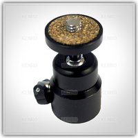
to mount em under the car will need afew of these

Mini_Tripod_mount_ball_head_for_camera_tripod_ballhead.jpg_200x200.jpg
 
tried to find any 10mm mdf, hardwood or preferably plastic but found none. so tried to drill some 2.5mm cardboard but that was a waste of time cos it was a right mess to machine due to its fibrous pulpy construction, binned

DSC07809.JPG


but then i saw some placemats on the dining table. thought it was wood but turns out to be plastic. perfect :)
marked the holes

DSC07810.JPG


my garage is a right old mess with all this drilling
(ps: the trick with drilling plastic is to alter the cutting profile angle of a spare set of drill bits on the grinder where the tip "scrapes" the plastic material off rather than "chisel/slice into" like normal bits. it'll cut cleaner n without snagging)

DSC07811.JPG


all holes precisely drilled 10mm n chamfered with the countersunk bit.

DSC07812.JPG

DSC07813.JPG


fill all the marbles on the holes. now leaving it exposed like this is asking for trouble cos the plastic is too shallow so the balls can easily be knocked off (less of a problem if i had some 10mm thick plastic)

DSC07814.JPG


so have to place the other piece on top to contain all the marbles (good thing i drilled both plates together to keep the holes aligned)

DSC07815.JPG


taped the edges, balls can still roll freely

DSC07816.JPG


good thing the placemats are the same size as the thick blocks i cut

DSC07817.JPG


next cut the 500x500 steel into 25x25 squares

DSC07819.JPG


screwed n countersunked onto the plateform wood

DSC07821.JPG
DSC07822.JPG


one complete uni-directional platform

DSC07823.JPG
DSC07825.JPG


nice. I'm aching from all that work but the luvely precision made parts are so worth it :)

DSC07826.JPG


tested it on one of the wheels, other side was on axle stand, and wow it works flawlessly :cool:


right drilled the 2nd set of placemats

DSC07827.JPG


taped

DSC07828.JPG


pair of turntables ready

DSC07830.JPG

DSC07831.JPG
 
Last edited:
last thing to make is the laser jigs

the plastic laser levels have two small screw adjusters at front & rear of the emitter to adjust its angle so I just need to strap it down onto the wooden jig.

gonna ziptie the laser onto the wood but first I cut grooves at the bottom for the ties to slip into to maintain a flat base when I plonk it onto the countertable for calibration

DSC07832.JPG


laser ziptied

DSC07833.JPG


now the base of the wooden jig is slightly convex so could rock via the centre but its gonna be mounted on the alloy only through the tip edges so I propped both ends up on the calibrating table with two washers of the same thickness and continue calibration

DSC07834.JPG


rather than ziptie the jig onto the wheel spokes and relying on friction to hold it in place, which will pull & bend the middle of the jig and affect the laser alignment, I made a metal hook that'll both hang via the tread groove and use the jigs weight to pull itself against the alloy rim

DSC07835.JPG


see here it pivots on top of the tread and the jig CG keeps it in contact with the wheel


got summore steel flats n finished the other hooks

DSC07836.JPG


here I'm hooking the laser onto the rear wheels

DSC07838.JPG


and the ruler at the front wheels. now this is before setting the wheels up on a level platform but i can already roughly spot the rear axle is pointing more to the right abit causing some crabbing and left steering pull

DSC07839.JPG


ok tomorrows the last job which is to setup a level platform for the car to sit on (with a bucket of water, long clear hose and a stick) before we start the alignment :)
 
Last edited:
Meh it works and tis all that matters.

When i get slicks? Ya mean the federal RS-R 595 semi, continue the same process of collecting data, analyse, adjust setup, test drive, rinse & repeat. And in the process maybe hold breath from the Gs, bigger smile and hope i don't soil myself
 
before i align the wheels tomorrow I I'll need to plan the method and calculate what readings to aim for

very first step is to place her on a level platform, apply my body weight ballast in drivers seat and adjust tyre pressures till the rim to floor distances are equal cos each tyre has slightly different tread depth and sidewall stiffness.

I've measured the front & rear tracking to find the offset distance 20.5mm between the front & rear wheels. the wheel base is also 2350mm

1. tracking & base measurement.jpg


now we need to align the rear axle first cos due to the panhard rod of a solid beam axle, it could be shifted laterally offset relative to the chassis & front wheels.
This could affect front wheel alignment cos they refer to the rear wheels.
if the rear axle is off-centre, the car will crab.

2. rear axle crooked.jpg


so we centre the rear axle to the chassis (adjust panhard till the rear wheel rim to wheel arch lip are equal both sides)

3. rear centered - off angle.jpg


then point the rear axle straight towards the front wheels by adjusting my whiteline trailing arms till the rear wheel lasers are both pointing the same distance away from the centre of the front wheels (not the forward/aft section of the front wheel cos that changes with steering angle)

4. rear centered - straight.jpg


with the rear axle centred n straight, front wheels on turn tables and the steering wheel locked pointing straight, we can begin straightening the front wheels

5. front crooked.jpg


adjust the trackrod ends till the lasers pointing dead straight at the correct distance away from the rear jig.

6. front straight.jpg


when the front wheels are dead straight the lasers should be pointing 41.5mm from the rear wheel jig (laser emitter to base offset + front/rear wheel offset)

7. front to rear offset.jpg


now if we wanna apply any additional toe in/out from the "Straight" position we calc how far the laser should point away from that.

because the laser and wheel rim are actually offset from the kingpin steering axis we need to calc this offset (kingpin to rim offset + thickness of jig + height of laser = 184mm)

8. front geometry - laser to kingpin.jpg


first calc is how far away from the "straight reference" the laser should point (offset from straight position)

9. calc toe offset from straight.jpg


but the wheel & laser jig actually pivots via the kingpin steering axis and this induces an additional offset distance

10. calc extra offset.jpg


so the total offset distance on the ruler that the laser should be pointing for any toe angle is (41.5 + offser from straight position + extra offset)

11. calc total offset.jpg


plotted the calculations and seems to be a linear increase per toe angle

12. offset reading per toe angle.jpg
 
Last edited:
made a camber measuring plumb-line

DSC07843.JPG
DSC07844.JPG


now to setup the level platform with a bucket of water and a long clear hose.

DSC07845.JPG


one end of clear hose taped to a stick used as the measuring probe

DSC07846.JPG


the other is submerged in the water. syphone water through hose till the level matches the bucket

DSC07847.JPG


place the car onto the level platform

DSC07848.JPG


now I adjust the tyre pressures till the height if the rims off the floor are all the same (full fuel tank & no driver or passenger weight cos i don't have any helpers).

start off all the tyres at 3bars cos thats how much it used to run when warm but this causes all the heights to be irratic due to different wall stiffness and tread depth between the tyres.

front left was the lowest while the rear tyre at 3bar were alot higher with the lighter rear end.

so i deflate the tyres till they match the front left tyre with the lowest height and the pressures are:
FR - 2.57bar
FL - 2.97bar
RR - 1.78bar
RL - 1.55bar

DSC07850.JPG


the turntable works so well. the handbrake is holding the rear wheels to the static floor but i could easily rock the front end side to side with ease


next is to center the rear axle. place the laser jig facing vertically on the rear wheel and measure the distance from the edge of the wheel arch, both sides are 30mm so no need to alter the panhard rod :)

DSC07851.JPG


to straighten the rear axle I point the lasers at the front jig at measure the distance from the middle of the front wheel.

initially the rear axle was showing 34mm on the left and 30mm on the right = rear axle was pointing 0.049deg slightly left.

extended the RH trailing arm till its pointing straight, both reading 32mm. I calculated the rear axle has a toe-in of 0.17067deg.

the rear camber measured 0.8deg rear left and 0.7deg rear right.

DSC07852.JPG


to secure the steering wheel, I engage the steering lock and apply pressure with zipties

DSC07853.JPG


next is to set the front camber.
initially even though both of the pillow tops are set at the same position (damper adjustment knob is 25mm from the edge of the strut hole), the actual wheel camber was 1.6deg front left and 0.6deg front right
(I suspect it might be caused by where the suspension strut bolts to the hub cos there's alot of available slack before the bolts are tightened which will alter both the hubs camber relative to the strut camber, abit like how camber bolts work but not intended)

I adjust the "damper knob to edge distance" till both wheels are 0deg camber and log the measured camber of each setting position:

LH camber for each damper knob position:
18mm = 0deg
28mm = 1deg
37mm = 1.8deg (can't go any further)

RH camber for each damper knob position:
7mm = 0deg
18mm = 1deg
26mm = 1.8deg

I've set both wheel at the maximum 1.8deg cos she tends to wear the front outer tread more

the camber adjustment top measures 650mm from the lower kingpin so I could calc any camber i need at the track using basic triganometry

dsc07856s.jpg


now I place the lasers at the front and align the front wheels dead straight

DSC07854.JPG


after they're straight, I got dad to sit in the drivers seat to see if the extra offset weight affects the alignment, nope they all remain the same, gr8

DSC07855.JPG


k all done. thought I'd return the cold tyre pressures back up to 2.85bar rear/2.8bar front as I ran before.

on first test run she travels dead straight when the steerings straight and minimal LH pull at low speed on open level roads (housing street roads have huge camber that obviously makes the car drift left) but at motorway speed she still drifts left abit (motorways have alot of camber too?)

I think that having the left & right tyres at the same pressure creating a mismatched rim-to-floor height (front right & rear left tyres have stiffer walls & is higher than the others apparantly) is causing the alignment to drift slightly left.

so I set the warm tyre pressures back to the values I set before alignment, where all 4 wheel rims will be equal distance off the floor, and the high speed drift is so much less or vanished now (depending on the camber of the road)

so i believe that's it, goal achieved :)
 
Last edited:
I also turned the steering wheel at full lock left and measured the angle of the top plate relative to the lower plate for both wheels.

the outer RH wheel turned in 27.5deg while the inner LH wheel turned 34.5deg

giving this geometry

full lock zero toe steering angles.jpg


the ackerman geometry of the rack should normally aim both wheels at the same point during turning but with the wheels currently set at zero toe, it seems to be toeing-in too much during turns.
will prob need bout 0.5deg of toe-out to correct it.
I'll do it after I replace the tyres (will need to soon cos they're at 2.25mm and apparantly its gonna snow abit this week :/) cos cba at the mo :p
 
Last edited:
abit snowy tday, perfect for testing if the LSD is working with the low preload.

went for a long drive to fully warm up the gearbox before any launches, most of the weak snow has dissolved in the rain.

so I setup cameras on both wheels, handbrake on (obviously wasn't on hard enough :p) and the first launch was by suddenly dropping the clutch. both wheels are slipping same time together so the ramp is working fine under high load, left wheel had a very slight stutter.

2nd launch was a more progressive clutch release and again both wheels spinning together


i think why it's wheel spinning out of a t-junction exit is cos the inside wheel had less weight on it from that suspension strut drooping down to the lower tarmac due to the camber at the side of the intersecting roads.
roughly the same torque was initially applied to the wheels but obviously the unloaded inside wheel spun more easily. once it began to spin relatively faster than the outer wheel, the LSD clutch had to work hard with the low preload and the available load coming from the ramp to try match both wheel speeds.
 
to make the coilover droop limiting covers I'll need a sewing machine.

mom had 3 machines from a basic old plastic one to a modern plastic multi-pattern one to this ancient singer with loadsa functions. thought I'd share the pics cos this things a mechanical beauty :p weighs a ton, made of proper cast iron, oarhh :D

DSC07869.JPG


needle won't travel fully down cos the bottom spool mechanism seems to be stuck. when I have time, would luv to overhaul it all like polly1. can't be as complicated as an engine :)

DSC07859.JPG
DSC07860.JPG
DSC07861.JPG
DSC07862.JPG
DSC07863.JPG
DSC07864.JPG


probing inside i found the plastic pinion gear that connects the upper crank to the lower mechanism has broken teeth. will eventually replace or dremel a new metal one.

DSC07868.JPG
DSC07865.JPG


now lets make a rough prototype out of an old shirt

DSC07870.JPG
DSC07871.JPG


sew the lower loop (where I feed a jubilee clip through)

DSC07872.JPG


feed up through a solid ring (sits at top of strut) and sew the outer layer to the inner layer of the cover

DSC07873.JPG


joint the vertical seam

DSC07874.JPG


there we go, one mockup strut cover

DSC07875.JPG


the top ring sits on top of the coilover

DSC07876.JPG


while at the lower end is a jubilee clip.
when it's fully open, the strut has full bump/droop travel.
but when you tighten the jubilee clip when the suspension is at static ride height, it clamps the fabric to the ring below the spring seat so limiting droop travel

DSC07877.JPG


the excess lower fabric is to cover the rest of the coilover threads from muck

DSC07878.JPG


but here's a weak spot for accessing the jubilee. gonna refine the concept to be stronger, thats the point of mockups

DSC07879.JPG


also my deltaTRAK 11063 needle probe thermometer's arrived, neat little toy with a sharp thin tip. only measures at the very tip and can probably dig well into a soft hot tyre tread so all good

DSC07882.JPG
DSC07883.JPG


testing it with iced water and me hot tap, seems accurate n responsive enough

 
Last edited:
cutting slot holes for inserting the jubilee inside the cover fabric will weaken it

so why not just simply create a sort of stopper at the end of the fabric (thicken it up with more fabric or o-ring) to prevent it slipping up past the gap between the jubilee clamp and the coilover ring

DSC07884.JPG


so made this

DSC07885.JPG


roll up the lip to thicken it up

DSC07886.JPG


ring fits over the coilover

DSC07887.JPG


so here the jubilee would clamp the fabric against the smaller lower coilover locking ring while the ridge stops the fabric slipping up. now it stops the spring & damper extending further and limit droop

DSC07888.JPG
DSC07889.JPG
 
Last edited:
came here looking for some info on water coming in to passenger foot well and sat reading through the rebuild blog on page 1. Absolutely fascinated by all the work done and was glad to see pictures of what I hope is my problem - under the wiper scuttle panel. I had originally thought it was coming in via the heater blower resistor as I had it out to solder as the blower wasn't working. Haven't used it for a couple of weeks and it was like a swimming pool today. When I started her up I heard the water sloshing about (in the heater box?). Hope to have a go at it at the weekend! Thanks again for your step by step instructions which I'm sure will come in handy :)
 
came here looking for some info on water coming in to passenger foot well and sat reading through the rebuild blog on page 1. Absolutely fascinated by all the work done and was glad to see pictures of what I hope is my problem - under the wiper scuttle panel. I had originally thought it was coming in via the heater blower resistor as I had it out to solder as the blower wasn't working. Haven't used it for a couple of weeks and it was like a swimming pool today. When I started her up I heard the water sloshing about (in the heater box?). Hope to have a go at it at the weekend! Thanks again for your step by step instructions which I'm sure will come in handy :)

thx for the compliment summerisle ;)
glad it was useful.

the motor and resistor card seem to be right in the firing line of any water ingress so prone to corrosion n failure.
important to check the motor is spinning freely and not too corroded first.
cos the water n dirt could eventually rust/seize up the motor bearings/bushes etc, which reduces cooling airflow through the card, increases loading on the resister card, both which rapidly heats it up till it burns out thus repair or place card.
 
tday we change tyres. been ringing around bout how much they are to fit if i supply the tyres, blimey heck it used to cost me £30-40 but now everyones quoting least £58-68!!:eek:
need to check if the tyre place can order & fit T1Rs (or most probably federal rs-r 595 in summer) instead next time and how much compared to buying em myself seperately and they fit.

beforehand I thought I'd measure the tyre thicknesses to know how much rubber i have left to prod the needle thermometer through before puncturing.

DSC07890.JPG


16mm from the tread to the unner carcass. the sidewalls only 8mm and quite flexible soft.

P9134282-1024x768.jpg


but looking at the section cut of a tyre from here the carcass ply belts seem to be much closer to the bottom of the tread depth. so prob measure the tread depth and probe the warm tyre no deeper then that

out of interest, the old tyre was made on 44th week of 2011 (30/10/2011. I ordered em on 6/2/2012) while this new set was made on 29th week 2012 (15th or 21/07/2012. I ordered em on 08/12/2012).

DSC07891.JPG
 
Last edited:
thx for the compliment summerisle ;)
glad it was useful.

the motor and resistor card seem to be right in the firing line of any water ingress so prone to corrosion n failure.
important to check the motor is spinning freely and not too corroded first.
cos the water n dirt could eventually rust/seize up the motor bearings/bushes etc, which reduces cooling airflow through the card, increases loading on the resister card, both which rapidly heats it up till it burns out thus repair or place card.

is there a correct/wrong type of sealant to use when fixing the seals - would this one do the trick?
http://www.idealsealants.com/siroflex-polyflex-hm-polyurethane-sealant-pu-black-310ml_c24p58.php
 
yep that'll do.
make sure the surfaces are clean, grease free and dry (keep it indoors or make sure it won't rain for 24hrs or just put a cover over the car). just need a thin continuous bead around the sealing lip enough to fill the gap with minimal excess.

sealant cures from the outside inwards upto a certain depth. if its too thick the insides won't cure (as I once found out by trying to fill an engine mount full of sealant) but for bonding surfaces to surfaces tis fine.
 
well, i went to national tyres who said on phone they'll fit em for £60..nope fella says he can't fit other ppls tyres:rolleyes:
he suggested hodgsons down the road..but thats a MOT service centre who then suggested walking next door to T.E.S. tyre place.

nice fellas, Lee and Jackie. said they'll do for tenner each, gr8

got em fitted and he said just give £30 :) prob the small talk eh
he suggested i give him call next time see if he could order the specific tyres for me and could end up cheaper than buying seperate.
cool sorted. think one of the alloys leaking abit on the way back. keeping an eye on pressure

with the wheels dead straight and the new tyres of equal height & pressures, she drives down the motorway dead straight no drift :cool:

i think a new thicker tyre with its releasing agent is slightly less grippy on the snow ice than the old thinner worn-in tyres

spinning the wheels in the back alley to test the LSD again, I notice if both wheels are on ice then yeah they both spin equally but if the right tyre is on the melted ice tarmac while the other is on ice, it'll just spin the left wheel no matter how much torque. so preload not quite enough
 
i think the tyre pressures been ok overnight although prob need a better tyre pressure gauge cos initially this tesco digital gauge was reading 2.75bar but when I double checked the same tyres it rised to 3bar (what I pumped yesterday)
so need to look for a more accurate consistant analog gauge with a better gauge-to-valve fit cos this digital plastic one is a pita to seal correctly, else it just leaks loadsa air and affect the reading
 
tday the £5 thermometer from china on ebay arrived
http://www.ebay.co.uk/itm/LCD-Non-C...pt=UK_Kitchen_Accessories&hash=item4ab6d5cb4f

DSC07892.JPG


this one's much better than the expensive mapin one. the moment you hold down the button it begins to display a constant reading, just what i need.
no backlight to waste power but the number display is abit tiny

DSC07893.JPG
DSC07894.JPG


inside, the pcb is abit simpler plus its short so no need to cut it

DSC07895.JPG


prob the same IC components

DSC07896.JPG

DSC07899.JPG


a much better unit to begin making the IR system out of
 
Last edited:
haven't driven the car for few days, just doing a quick checkup.

since this tesco digital tyre gauge is getting abit inconsistant and due to its offside handle design, sealing against the valve is tricky, but i found that halfords digital pressure gauge with depth gauge I brought awhile back.

239116


it seals abit better, automatically starts reading when it senses pressure, big screen. although it only reads in 0.05bars whereas the tesco gauge reads in 0.01bars, it'll do.
measured all the tyres from being left over the weekend and they're all bout the same so no leakage.

usual wirebrushed the dizzy cap contacts.
looked at the plugs and they're perfect

DSC07901.JPG
 
Last edited:
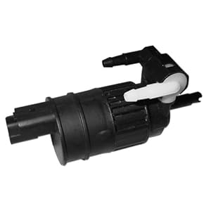
my washer pump have always been getting weaker and the rear jet leaks when I use the front jets.
think the motor's getting submerged in liquid again and the 1way valve is broke so need to replace.

thing is that a pre-face k11 washer pump on ebay is least £17.50 (of unknown reliability) but a trip to halfords I see what seems to be a facelift plugged pump for just £17 new and I'd rather get a new one tbh

DSC07908.JPG

DSC07909.JPG


my question: is this a facelift connector?

DSC07910.JPG


if so, then I'll cut off a connector plug out of a facelift in the scrappy and solder it to my loom
 
Last edited:
I can get you a pic of the back of a facelift pump if you like Paul i've got one sat in the garage (dont run screen wash)

for verifying the connection that'd be gr8.
actually will u ever be using the washer system on that chassis/loom?
abit cheeky request :p but just wondering if you'd be willing to sell the pump and snip off the loom connector if it'll never be used.
 
for verifying the connection that'd be gr8.
actually will u ever be using the washer system on that chassis/loom?
abit cheeky request :p but just wondering if you'd be willing to sell the pump and snip off the loom connector if it'll never be used.

Your welcome to the pump Paul I'd just like to keep the connector incase I went back to screen wash for rallying, I'm pritty sure I have a spare preface lift washer pump as well if that's any use to you
 
Your welcome to the pump Paul I'd just like to keep the connector incase I went back to screen wash for rallying, I'm pritty sure I have a spare preface lift washer pump as well if that's any use to you

just thinking, selling the pump plus postage will prob cost as much as if I buy that amazon pump eh?

ah I think the original plan of buyin £10 amazon pump & snip a facelift plug from the scrappys prob my best bet.
better to snip a connector of a k11 thats gonna be crushed anyway than a k11 that's still in use
 
checked the battery with multimeter and hmm its 11.89V abit low. so briefly hooked a charger to it before driving. actually better to just drive it to charge, so after 10min twas at 12.6v

do my preflight checks, tyre pressures all the same as before, oil good, ah coolants dipped 2mm due to cold..ok lets top up.

saw a nissan coolant bottle nearby, began pouring into the expansion tank when I thought, this coolant's abit thick? oh ffs it bloomin oil! and I labelled it OIL too dummy, must be the cold

may as well flush n wash the tank out

DSC07911.JPG


clean n refilled

DSC07912.JPG


started her up and hmm thats odd. after cranking, the lights vanish as normal but then the battery light slowly fading on. uh-oh never had that before.
blip the throttle, it dims a tiny bit but keeps on getting brighter till its fully on, crap is the alternator packing up?
another blip and it goes out, gr8 we got voltage, maybe slipping belt?

DSC07913.JPG


so looked at the belt, nope still spinning no probs no noise but then noticed the rotor slip ring bush at the back was sparking away. think the graphite bush is on it's last legs, spring fully extended cos u can see it barely trying to wear away that brown surface rust (like u get on brake discs after standing in moisture for awhile) that's preventing full contact

DSC07914.JPG


consult shows its making 13.87V rather than +14V so yeah tis getting old after 15yrs n upto 200k miles

after a drive down the motorway n back its fine n not sparking.
 
Last edited:
would be gr8 if I could use all four of my digital scales during corner weighing.

previously I placed a beam across 2 scales and added the values up, which worked well but i only have 4 200kg scales and would waste time swapping em back to front and have to re-level the platforms or it'll affect consistancy.

saw this suggestion of a lever pivot scale but it requires absolute precision to be consistant.
even if the wheel centre is off by 1mm along the beam, especially with a short beam, it will knock the reading way off.
I mean standing on a beam between 2 scales, if i just shift my body CoG slightly, the readings change alot

weight1.jpg


found a better mechanism, think it's called a ruggles aircraft scale, I'll be looking into.

the balancing tray levels itself to the bottom of the wheel independently to the beam angle and focuses the wheel/tyres weight at the same single measured point along the beam.

the 3-point tripod beam also focuses all that weight at a single set point on the scales

all of which helps maintain consistancy

wb2.jpg
 
Last edited:
here's my first design for making a ruggles scale

the wheel rests on a rocking platform (green) which pivots at a specific point (1/4 or 1/2 way) along the frame (yellow), so the camber of the wheels won't affect the position of where the load is applied on the lever equation system.

the lower end of the frame rests on the tarmac at whatever level that section is at.

the upper end of the frame would contact the load distributor H-frame (red) at a narrow middle region within the bathroom scales footprint (so even if the lower end of the frame was at a different odd angle relative to the scales, it'll still focuses the load through the middle of the scales)

the digital scale is rated to support 200kg but prob not through a pinpoint.
so a load distributor H-frame (red) spreads the load out above the 4 bathroom scales feet, where the loads are measured and combined, rather than focusing 150+kg straight through the middle of the glass between the feets and potentially cracking it.

the scales sit on a flat hard tile/plate above the tarmac cos the uneven tarmac would affect the overall accuracy of the scales piezo sensors

ruggles scale2 (1).jpg
ruggles scale2 (2).jpg
ruggles scale2 (3).jpg


wheel platform with the L-bar below forming the pivot point

ruggles scale1 (5).jpg


the beam frame can have 2 grooves that the wheel platform can sit in to divide the load to the scales by say 1/4 or 1/2

ruggles scale2 (4).jpg


load distributing H-frame for the bathroom scales

ruggles scale2 (5).jpg
 
Last edited:
the wipers were getting abit weak in clearing the screen, hazy and shutter abit, tried tightening the arm spring but no effect.

so went to dealers for a new pair, they've now shot from £10 to £20 each but simon offered em all for £15 ;)

alot better now. guess the rubber hardens abit quicker towards the winter months and that colour changing indicator sticker on em are useless.

also mentioned to him bout my leaking rear crank seal and maybe inlet stem seal, he said Just a min...
went to grab a box full of old redundant bits for me to delve through and I could have any of it free n see if it fits cos they were gonna be binned anyway but he kept a box of em just incase. nice one simon :)
most were for other old engines but found loadsa packs of stem seals and another which looked like a front crank seal. grabbed a handful of bits like candy :p

the valve stem seals were 13207-84A00 but looks like they're for larger GTI, primera, sr20de engines, meh

DSC07915.JPG


this crank seal looks familiar, code 13510-1F700

DSC07917.JPG

DSC07918.JPG


checked with the one on my forged engine, same. excellent a free main seal :cool:
was hoping to find a rear main seal but hey they're free :D

DSC07919.JPG
 
Last edited:
figured the 25x25x1.5 square tubes can cost from £4.65/metre online
25x25x1.5mm L-corners from £6.17/metre local B&Q
40x40x3mm L-corners from £10.89/metre online
500x500mm steel panel £11.88 local B&Q

the first design of the ruggle scales with the red H-frame on top of the scales used in total
12.76m of 25x25x1.5mm square tube
1.58m of 25x25x1.5mm L-corner
225x250 x4 sheet steel
total = estimated approx £81 worth of material
(but since u can only buy in 1/2/3/6m lengths it'll prob be abit more upfront)

wonder if removing the H-frame can reduce material & cost..

to keep the load closely over the scales feet, I turn the scales diagonal so the frame sits on it aligned overhead the sensor feet

rugglesscale4b4.jpg


simplified the frame abit to make it easier to weld and raise the frame up away from touching the sides of the scales

rugglesscale4b1.jpg


need to use a bigger 40x40x3 L-section to keep the platforms pivot point aligned between where the frame rests

rugglesscale4b2.jpg

rugglesscale4b3.jpg


altered frame

rugglesscale4b.jpg


so this design uses in total

9.2m of 25x25mm square tube
2m of 40x40x3mm L-corner
225x250 x4 sheet steel
total = estimated approx £76.66 worth of material

saves a fiver and easier to make :)
 
there's 2 issues with the prev design:

1- the garage wall is at least 40cm away from the tyre wall and the long frame makes the diagonally placed scale stick out too far

2- the square profiled ends of the frame meant it can only be orientated one-way cos the position of the platforms pivot point is fixed (easy to mess up the reading unless labelled or its inconvenient)

ruggles scale5 (1).jpg


to address issue 2, both ends of the frame and the pivot that the platform sits on are all the same 25x25x1.5 L-section

rugglesscale6.jpg


so it keeps all the pivot points aligned and with the corrent distance apart, whatever the orientation or angle of the frame

rugglesscale62.jpg


the frame was also shortened as much as possible to resolve issue 1

rugglesscale61.jpg


but just long enough to prevent the edge of the digital scales from hitting the tyre platform if say the height of the scales were stacked up alot to lift up the tyre platforms height during the water levelling procedure

rugglesscale63.jpg


this design uses in total
6.96m of 25x25x1.5 square tube
4.6m of 25x25x1.5 L-section bar
a 500x500x1.5 steel panel

total = £72.63
 
Last edited:
using a smaller 15x15x1.5 L-section at £3.49/metre compared to £6.17/metre for the 25x25x1.5 L-section will further reduce the cost to £60.30:cool:

rugglesscale7.jpg
 
so after figuring out the jigsaw of how much bar to order, which section to cut with the least amount of wasted off-cut

(example of a 2m tube at top, and how much to cut off from the 4 tubes)
fittingtubes.jpg


I've calculated I'll need:
4x 25x25x1.5x2000 square tube = £39.85 delivered on ebay
http://www.ebay.co.uk/itm/290813735634

5x 15x15x1.5x1000 L-corner = £17.45 from B&Q
http://www.diy.com/nav/fix/hardware...00mm-x-W-15mm-x-T-1-5mm-9283740?skuId=9293440

1x 500x500x0.6 sheet panel = £11.88 from B&Q
http://www.diy.com/nav/build/buildi...oloured-L-500mm-W-500mm-9284137?skuId=9293837

so all the material & offcut will cost me £69.18 up front.
(the 96cm of square tube off-cut left over worth approx £4.82 can be used elsewhere)
 
well some good news job-wise..

yesterday went to an interview with me workm8 about getting 6mth funding for setting up his business (which I've been helpin out in building several product demo's to show em) and tday we've been granted funding to start the company from feb, so yeah I have a job :)
 
ordered the square tubes and more mild steel arc rods.

checked out the steel bars in b&q.
the 25x25 square tube seem to hold well with minimal deflection.
the 15x15 L-section is tiny and too flimsy tbh
a 25x25 L-section was much stiffer
suppose a 20x20x1.5 L-section is just stiff enough, increases the cost abit by £14.18 to total of £83.36

edited the model with the 20x20 L-bars

rugglesscale8.jpg


also chamfered the inner edge of the platform frame to clear the edge of the digital scales

rugglesscale81.jpg

rugglesscale82.jpg
 
A-ha just figured a cheaper configuration..this continuous refinement of mine just never stops eh :p

Since the square tubes are much cheaper per meter than the L-sections, why not just angle em at the ends of the frame to offer that V-pointy feet (keeps the pivot points consistant) and better stiffness than any L-section bar.

rugglesscale9.jpg

rugglesscale91.jpg


The end of the diagonal bars would be half cut like this to fit onto the main beam of the frame

rugglesscale92.jpg


It uses 9.36m of 25mm square tube and 2.2m of 25x25x1.5 L-section bar and a 500x500 steel sheet.
Total £68.98 of material

lets hope I don't find another improvement :p
 
Before balancing or cornerweighing the car again, I'll need to load it up with 75kg of driver & passenger weight.

Iron dumbells are at least £1.23 per kg.

Vinyl dumbells are at least 67p per kg but unavailable.

Rice is £1.10 per kg

But the cheapest by far is bulk buying cement at 22p per kg
(25kg bags at wickes, buy 5 bags for £3.83 each)

So buying 6 bags of cement for £25 should do the job :)
Hope i could return it back after use :p
 
well tday the 4 25x25 square tubes and another pack of steel electrodes arrived so I can get on with making the ruggle scales

DSC07920.JPG


got 2.5m of 25x25 L-corner and slightly more expensive 500x500x1.0 sheet steel (the 0.6 gauge felt too flimsy to support a tyre)

DSC07922.JPG


also checking around b&q, sure enough the 25kg cement bags are £3.53 each when buying more than 3, but then I spotted some building sand that says 5.2p per kg!
that's only when buying over 10 bags, but even without the discount its still 7.1p per kg = £10.68 for 6 bags totalling 150kg.

now that's a bargain for weighing down the car during balancing :D

DSC07921.JPG


phoned local scrappy bout a used alternator and he quoted £25 + vat (£30) :/
suppose in the yard I could remove the cover n assess the slip ring bushes (compared to buying online) before forking that much out, but unfortunately there're all facelifts so no alternator. may as well buy a cheap one online that's preferably off a lower milage pre-face.

also grabbed a facelift washer motor plug, awaiting new motor from amazon

DSC07923.JPG


now fixing my mitre saw with a cutting disc to cut the tubes...

tubes marked. prob abit late to be cutting metal so will do it tomorrow
 
Last edited:
You arnt still buying your metal from Ebay are you Paul?? There must be a steel merchants somewhere near you surely?
Looking forward to seeing the next Paul Special take shape :D
Gotta love the work you put in!!
 
Back
Top