• Please only use these forums for blogs, they are not a discussion forum

PollyMobiles Rebuild

last time i waited a month for parts were my janspeed manifold and bilstein streetline kit from rallynuts on seperate occasions and almost happened the 3rd time with the janspeed catback from rallynuts till i had enough n ordered from matt humphris and was delivered next day.

I'm desperately hoping that ordering direct from JE will be substantially quicker with whatevers the fastest courior option is. don't care how much extra it'll be now. after waiting a furious month, I'd fly over there to get it myself if i have to:rolleyes:

to buy from JE would be bout £65 set of rings + £60 delivery + import tax customs, admin fee, courior, etc
 
Right, ordered set of XC7150 from JE $66
they do either $33 3-5day delivery or £99 overnight 2-5days delivery, chose overnight obviously
so $166 = £105 meh

hopefully they'll have some in inventory if not then its custom made and then shipped overnight over next few days.
hope its not another month :Z
 
Mmm yea donnington. not been on it yet. won't be able to get the car ready in time for japfest on 9th. £130 for a whole evening on 20/26th july eh
 
first rough design of the windage tray using louvres

scaled.php


integrated crank scrapers

scaled.php
scaled.php


it'd fit like this

scaled.php
scaled.php


I'm not too sure on the louvres. cos they're always open i feel it won't prevent the oil from sloshing left and up past the louvres. If i brake really hard it seems the front louvres will just allow the oil to scoop upwards.

i feel i should use hinged gates so during high G the loaded gates shut n prevents the oil sloshing up
 
ah i shoulda thought bout removing this bump at the LH of the sump like in this pic

Showing_length_of_sump_indent_rwd.jpg


and ask ed to weld a plate over it cos it'll give some space below the already confined LH girdle for any trapdoor gate. i read the bump is mainly for easier access to the auto torque converter bolts?

ah well nothin i can do bout it now :/
 
yay the welded sumps arrived back :) that's made my day

DSC06868.JPG


pickup plate meets nicely with the baffle

DSC06869.JPG


front

DSC06870.JPG
DSC06872.JPG


RH

DSC06873.JPG
DSC06874.JPG


back

DSC06875.JPG
DSC06876.JPG


LH

DSC06877.JPG
DSC06878.JPG


pickup plate tacked on with minimal warping

DSC06879.JPG
DSC06880.JPG
DSC06881.JPG


minimal distortion

DSC06882.JPG


thankyou Ed:D
 
Last edited:
btw paul, the little weld that goes off at an angle from the oil return fitting was where the metal had cracked (not sure if that was the way you made the hole?)... hopefully that has sorted it eh.
 
was thinking of this arrangement tday.
there's scrapers at the front & bottom of the girdle and the rear of the block. the bottom plates cover the girdle holes allowing returning oil and scraped oil to flow across and back down into the sump but tries to make it hard for the sloshing oil below from gushin up

DSC06883.JPG


but then i wondered how close is this bump to the girdle cage? measured n modelled the bump

louvre.jpg


OMG what a stupid design flaw. this bump is completely blocking underneath cyl4s crank girdle hole so can't drain out easily n pool up in that crater till it fouls the crank or spills out the sides. definately need to cut it out n ask ed to weld a patch over it
 
Last edited:
once the sumps been corrected to relieve the available clearance under cyl4 i think i'll develop towards this gated windage tray concept.

the gates at the front, back and bottom of the girdle cage allows oil to flow down into the sump but whenever the oil sloshes upwards from lateral/longitudinal forces it forces the gates shut.
have to figure how to custom fabricate the gates. they have an edge lip that rests on the top of the pickup baffle or bottom of the LH sump to only allow the gate to open slightly enough for oil to drain down yet responds to flow reversal

scaled.php
 
btw paul, the little weld that goes off at an angle from the oil return fitting was where the metal had cracked (not sure if that was the way you made the hole?)... hopefully that has sorted it eh.

just realised u meant the turbo drain fitting at the front. was looking round the oil pickup thinkin huh looks fine?

person who drilled that big hole made a rough hash of it. forgot to smooth it up myself.
wonder if that could have been a tiny source of leak previously?
thx for fixing it
 
Ed I'ma have a go at butt welding the plate on first. if it doesn't work I'll grind it back n post the sump over with a new plate
 
marked n cut the section off the sump using the ribbings as a straight guide. the sump is 1.2mm gauge while my b&q sheet is 1mm so just a slight difference

DSC06884.JPG
DSC06885.JPG
DSC06886.JPG


behold, a broken sump

DSC06887.JPG


fitted it on the engine to see how much room there really is and oh my just look at the lack of space. its a good thing I decided to banish this awful bump feature

DSC06888.JPG


eek

DSC06889.JPG
DSC06890.JPG


measured n plotted the model and jeez cyl4 has no drainage room at all :/

with this hole i can fit the pickup n new baffle and check how the pickup cover fits.
phwoa yeah i luv it when things fit precisely spot on:cool:

DSC06891.JPG


to make the plate i stretch some masking tape over the hole

DSC06892.JPG


handy backlighting to trace my pen along

DSC06893.JPG


place template on sheet

DSC06894.JPG


cut it just slightly outside the line so I can slowly file the edges to a closer fit

DSC06895.JPG


next is the patience game of filing, bending n matching the plate to fit hole precisely

DSC06896.JPG
DSC06897.JPG
 
Last edited:
when the plates ready I need a magnet to hold it in place when tacking.
figured i had this scrap harddrive, they have these very strong flat magnets, perfect

DSC06898.JPG
DSC06899.JPG
 
Last edited:
paul surely nissan with there highly qualified engineers didnt put that dip in for nothing? are you sure it doesnt need to be there?

saw afew racing threads n guides bout removing it for better oil flow.
seems the dip is mainly for ease of access to the back of the flywheel to reduce garage labour since the car was also engineered with low service cost and street running in mind rather than racing.
 
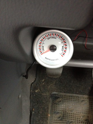
just thinking i should really fit an oil pressure & temp gauge shouldn't I?

Oil temp, oil pressure and rpm are the only 3 gauges getting any attention in my car :rolleyes:

Things like this become very funny on old classic car track days. People ask 'how fast were you going down the back straight?'. The most common response is XXXXrpm with the real old skool boys saying 'XXpsi oil pressure' ;)
 
^lol I'll prob be like that. hopefully not 7000rpm with 0psi :eek::D

ok good idea to get it done then. costs adding up. buying electronic oil sensors, gauges, tyres, alloys, rings, bearings, machining etc
 
Probably another one of those 'hook, line & sinker' moments lol :p

For most it's unnecessary but if you're going to track it and have spent money on a forged engine that you want to last it's a bit of a no-brainier to keep an eye on things and you don't have to spend a fortune on gauge bling either. Prices can quickly mount up that way :confused:

I'm very interested in the oil pump output profile on the CG engines....
 
yeah gonna get a low cost electronic oil temp & pressure sensor & gauges n find a gauge location thats within view n not an eyesore, hmmm...

forgot what psi haynes says the pump is. the pump output has a sprung loaded regulator and filter has a sprung bypass.

but i read that these cog type pumps are only efficient at a low range where they're usually intended to be used as street cars and that at very high revs they begin to lose efficiency, heat the oil up and begins to airate/cavitate the oil?
 
hmm came across an article bout oil accumulators. tis like a cross between a dry sump tank and pressure buffering tank in a central heating boiler.
the oil pump keeps the tank filled with few L worth of pressurised oil. when the pickup starves briefly, the accumulator continues feeding the engine with pressurised stored oil till either the pickup recovers or the accumulator tank runs out if its not big enough and say goodbye engine.

http://www.stockcarracing.com/techarticles/1594_oil_accumulators/index.html
 
yeah gonna get a low cost electronic oil temp & pressure sensor & gauges n find a gauge location thats within view n not an eyesore, hmmm...

forgot what psi haynes says the pump is. the pump output has a sprung loaded regulator and filter has a sprung bypass.

but i read that these cog type pumps are only efficient at a low range where they're usually intended to be used as street cars and that at very high revs they begin to lose efficiency, heat the oil up and begins to airate/cavitate the oil?

Workshop manual has the following specs for the CG13DE;

650-750rpm = 11.5 - 17psi
2000rpm = 43 - 54psi
6000rpm = 64 - 75psi

Given that most people seem to state 10psi per 1000rpm of crank rotation, I am looking into some ways to improve.

I know of a few people using Accusump accumulators, which are essentially the same as the moroso units.
 
i meant integrated into the interior and within easy glance like the pillar pods rather than lazily plonked somewhere but the pods are already full and i put my satnav in the lower corner below them.

maybe i should instead sacrifice convenience and put the satnav in the middle of the dash (i only use it occasionally when travelling long distances from home) while the oil gauges are fitted to the lower half of the pillar pod section? yeah I'll be doing that.
 
Workshop manual has the following specs for the CG13DE;

650-750rpm = 11.5 - 17psi
2000rpm = 43 - 54psi
6000rpm = 64 - 75psi

Given that most people seem to state 10psi per 1000rpm of crank rotation, I am looking into some ways to improve.

I know of a few people using Accusump accumulators, which are essentially the same as the moroso units.

yeah i saw the accusump in merlin motorsports. not cheap :/ another drain to my limiting budget

why go for more oil pressure than needed? would it not waste power unnecessarily? heard some ppl tighten the oil pump reg spring to increase pressure.
 
yeah i saw the accusump in merlin motorsports. not cheap :/ another drain to my limiting budget

why go for more oil pressure than needed? would it not waste power unnecessarily? heard some ppl tighten the oil pump reg spring to increase pressure.

Well to be honest, you're right as I consider the 10psi per 1000rpm to be only valid within a certain range and only to be a very rough figure.

I am far more interested in the oil pumps ability to deliver enough flow, so I guess we'll see how things go and if we run into any issues we'll work them out. I think the stock oil pump will stand up to what we throw at but we wont be taking any chances and including temp & pressures in the dash to keep a firm eye on them.
 
Workshop manual has the following specs for the CG13DE;

650-750rpm = 11.5 - 17psi
2000rpm = 43 - 54psi
6000rpm = 64 - 75psi

Given that most people seem to state 10psi per 1000rpm of crank rotation, I am looking into some ways to improve.

I know of a few people using Accusump accumulators, which are essentially the same as the moroso units.

Those figures pritty much match what my gague shows on a hot engine , more near 90psi @ just over 7000
 
Well to be honest, you're right as I consider the 10psi per 1000rpm to be only valid within a certain range and only to be a very rough figure.

I am far more interested in the oil pumps ability to deliver enough flow, so I guess we'll see how things go and if we run into any issues we'll work them out. I think the stock oil pump will stand up to what we throw at but we wont be taking any chances and including temp & pressures in the dash to keep a firm eye on them.

I agree
 
carefully filed the round section till it matches the sump then i marked n bent the fillet with a 22dia rod which turned out to be slightly off angle and a hard way of making & fitting the plate.
what i shoulda done was the opposite way. bend a flat sheet to form the curve profile of the sump first and then mark the shape of the hole from the inside before cutting it out.

DSC06900.JPG


grinded n cleaned the bare metal edges

DSC06901.JPG


tacked in place. when i've nervous n hesitate the arc strike, the rod either most likely sticks or makes a hash of a weld so i have to learn control the emotions, to be confident brave n go straight in straight out and have patience to let the weld cool abit before moving on.

DSC06902.JPG


first pass.
aint pretty but got easier as the workpiece preheats and kept the rod at a very shallow angle to prevent burnin holes.
found it also starts far smoother if i keep the rod tip hot between each pulse weld or i preheat the tip with afew strikes elsewhere till its glowing hot before I continue the welds

DSC06905.JPG


2nd pass

DSC06906.JPG


as long as i keep the welding pulses short and the cooldown inbetween slightly longer to keep the metal temps down, it welds quite alright

DSC06907.JPG


DSC06909.JPG
DSC06910.JPG


cam phone just ran outa power. quite pleased how it turned out. tomorrow will grind flat the dodgy ones n do a 3rd pass. weld it up from the inner side and its complete :)
 
Last edited:
this was the sump from last night

DSC06911.JPG
DSC06912.JPG


grinded n rewelded the bad bits

DSC06913.JPG
DSC06914.JPG


welded in inside

DSC06915.JPG
DSC06916.JPG


grinded of all the tiny spatters, ya don't want that stuff comin off n floating round the sump

DSC06917.JPG


sump wirebrushed n degreased

DSC06918.JPG
DSC06919.JPG
DSC06920.JPG


waiting for primer to cure now

DSC06921.JPG
DSC06922.JPG
 
Last edited:
this morning i thought my prev idea of using a large vane gate to control the oil flow from the bottom girdle cage hole was too inefficient especially near the shallow LH so had a rethink n simplify and came up with this.

*a rear scraper removes excess oil from the crank.
*the sealing flange between the sump & girdle funnels any oil from the outer sump walls down towards the bottom centre hole of the girdle cage.
*the oil collected through the girdle hole now enters a lower collection chamber divided from the next cyl, so the collected oil from cyl1 can't surge over towards cyl4 during turns, and is only allowed to enter the sump below via the front or rear 1-way swinging vane doors
*any unequal pressure spike on the outer side of each vane caused by oil surging around during Acc/Braking or Turning will cause that vane to close, preventing the oil from surging back up towards the crank yet still allowing the other unloaded vanes on the opposite side to flow

scaled.php


here's the modeled windage tray/baffle

scaled.php
scaled.php


fitted to the girdle cage

scaled.php


a horizontal cross section through the bottom plate so you can see the divided collection chambers under each cyl and the front rear vanes

scaled.php


close up of the swinging vanes. the hinge pin is secured in place by a slot hole in the side walls and the girdle cage above

scaled.php


how the front & rear flages seal against the sump walls. it keeps the pool of oil in the sump away from the moving crank area above

scaled.php


side profile

scaled.php


front cross section showing the seperate collection chambers under each cyl

scaled.php


side cross section of how the fron rear flange funnels oil into the girdle and into the sump via the vanes

scaled.php


vanes swing open

scaled.php


at the tighter LH with the removed bump certainly makes this concept possible. oil flows out the vanes and down the sides of the sump into the lower parts of the sump

scaled.php
 
i think what I'm doing is essentially converting a wet sump into kind of a dry sump where the mass of oil is seperated from the spinning crank and the oil is collected and fed to the sump via a central hole in the girdle cage with a one-way valve. (bit like a caravan loo eh lol)

the current shallow valve vanes at the front & rear seems abit too restrictive and cautious it might cause oil to pool up in the girdle cage especially at 7000rpm with 90psi oil pressure.
i need to figure out a simple vertical check valve that only allows oil to flow 1-way down through the girdle hole as freely as possible while the sump/girdle flange seperates the two areas.
 
k i've been sketching various sliding check valve layouts but thought it won't be reliable enough cos it could jam. wanted a more securely fixed reliable valve mech like the hinge and after hours of development came with this

*a divider flange thats bolted around the girdle cage, the extended front & rear gulley seals n seperates the sump from the crank while channelling the oil above inwards towards the girdle.
*pair of hinge vanes per cylinder. the dual opening allows oil to drain out freely irregardless of the lateral G direction, as oppose to a single hinge that'll only flow good in one direction.
*support bracket holds the dual vane pivot to the girdle cage and limits/stops the vane opening at 20deg so it can both allow enough oil to drain out yet able to shut quickly whenever the flow reverses during surges

scaled.php
scaled.php


fitted on the girdle

scaled.php


side profile with all the vanes open

scaled.php
scaled.php


say when i turn right and the oil surges left towards the elevated LH side of the sump, the vanes on the LH experiences reverse flow as the oil from the sump tries to surge up into the crank area. the reversed pressure difference pushes the large vane up and seals the hole to resist the surge

scaled.php
scaled.php
 
good news ppl. mom just rang that I've got a post from USA and had to pay extra £19, prob customs. YAY my rings have finally come:D:) thought sebastian meant the eta of 28th june was for his supplier to send it to them then they send it to me by fri but nope it's actually eta of 28th june sent to my door:D

can't wait to get home and then give to my machinist asap
 
Last edited:
Back
Top