Ma09ERT prep for install

Good day to all.
I have come to the home of the superturbo gurus for advice, guidance and education.
Also guys, feel free to express any and all of your opinions.

I have been trying to prep a ma09ert to swap into a stock K10 that came with the ma10 and 3 speed auto.
I plan to keep the auto tranny with the stock ma09 engine: no future mods planned.

My biggest forseen problems are getting the 1 million vacuum lines correctly connected as well as wiring the harness and ecu to work.

I have studied the vacuum diagram posted on the forum by Baz, but I don't see some lines like the ones that go to the vacuum box/chamber? on the intake? Working on them and will try to specify the ones I can't figure out.

This K10 also does not carry a tach as standard. I was wondering if it would be easy to locate the wires sending the tach signal to the dash as well as the ones for the supercharger light in the harness. My plan is to use an aftermarket tach and the shift light for the supercharger light as the car will be auto. Also, how/where do I power up?

Anyways, just really wanted to introduce myself today.

sleeper, here, representing ma09ert from trinidad and tobago.
 
welcome to the thread, baz.
i feel honoured to have your presence.

any tips or info to help me reach my goal would be most appreciated.
 
MA10 3 speed auto to MA09ERT 3 speed auto conversion.

The cause
Gas mixing with oil in stock MA10. Rear seal blown. Repair requires separation of engine and tranny to change rear seal and fuel pump gasket and/or carburetor would need service.

The proposition
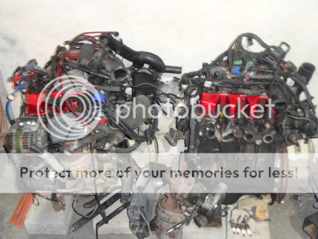
To install either one of two MA09ERT in my possession, which were acquired as upgrade spares soon after the car in the event that a situation like this or worse was to happen.
DSC00683_zps9e2efcb9.jpg


Action
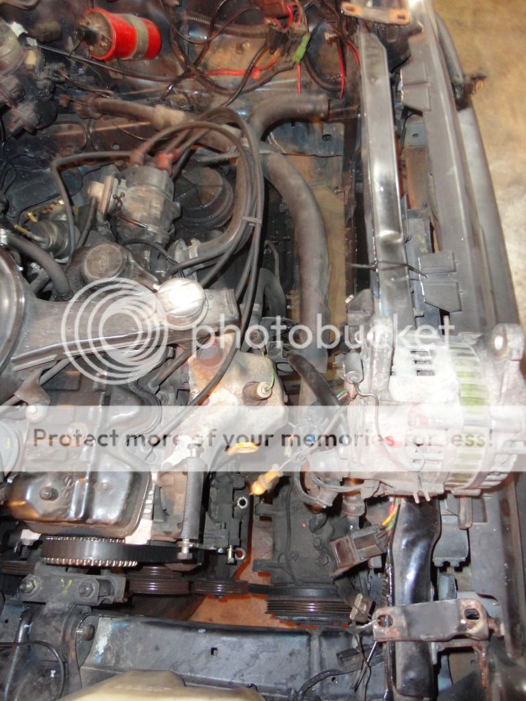
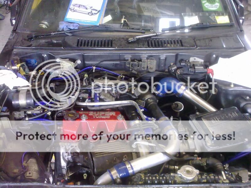
MA10 and tranny disconnected from vehicle and ready for lift out. The wires from the cars original harness for the oil light, temperature sensor were labeled for use with the MA09ERT and the known to be working sensors from the MA10 would be transferred across to the MA09ERT. The AC compressor and alternator were also removed from the MA10 and secured to the side, to be transferred to the MA09ERT with their original mounting brackets and wiring from the cars original harness.
DSC00681_zpsf3ec5ebd.jpg


The decision
It had to be decided which of the two engines were going to be used for the swap.

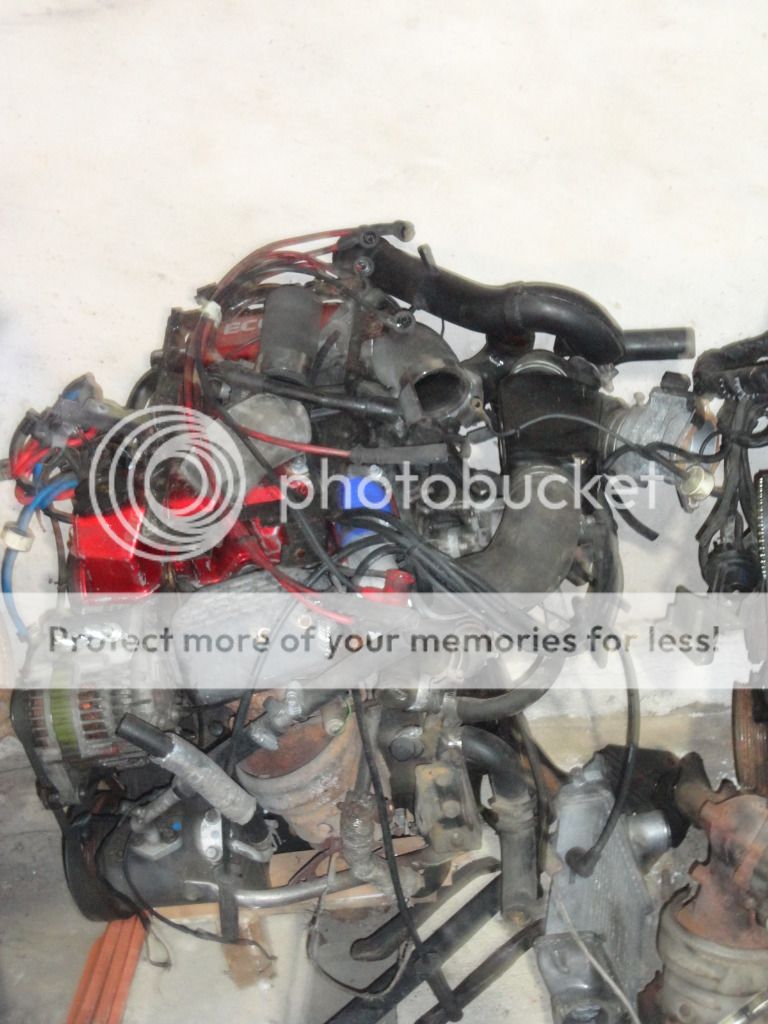
ENGINE 1
DSC00689_zps376514df.jpg


History
Acquired from a daily driver, supposedly a proper running engine.

Inspection
One or two sensors were abandoned, the coolant lines to the turbo were not connected, some vacuum lines were busted, spun over easily, had no.5 plugs, good ignition leads but connected in reverse firing order, all belts required to run the engine, more assembled engine.

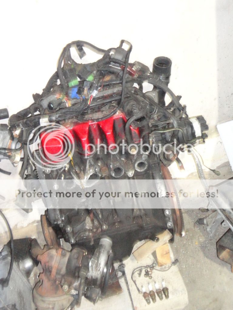
ENGINE 2
DSC00690_zps0795a1b6.jpg


History

Acquired from a front half cut of a superturbo. All externals were removed from the head and block as the previous owner was trying to make it fit in a mini. It supposedly ran for some 30 mins to 1hr in the front half cut before being purchased by the previous owner.

Inspection
Appeared to be a more original engine but everything mounted to the head and block was slack. It spun over easily, no. 6 plugs. One exhaust stud broke in the head and must be extracted and replaced. Some rubber piping couplers were not in the best condition. Some vacuum lines missing.

Comparison
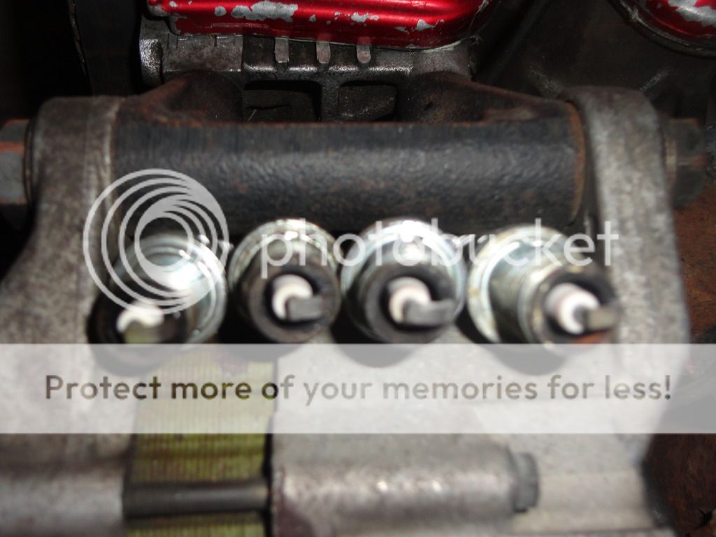
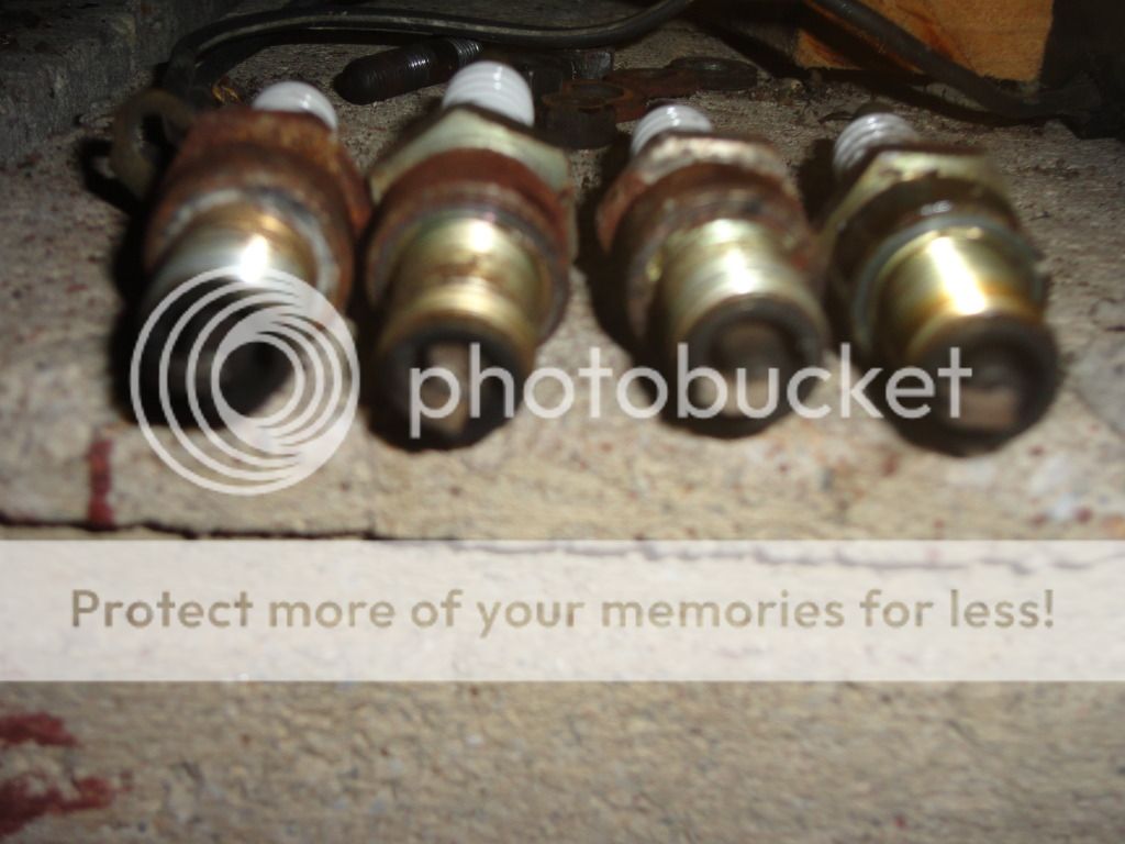
Comparison of engine plugs for an idea of engine burn characteristics and to try to identify any bad burning cylinders.

Engine 1

DSC00687_zps0b27f13a.jpg


Engine 2

DSC00686_zps98ed5e62.jpg

The two sets of plugs indicated a similar burn. 1 seemed to be the richest cylinder, followed by 4 then 2 then 3. All the plugs from engine 2 seemed to be in acceptable condition. The plugs from engine 1 showed some pitting on the electrode from cylinder 2 and more so cylinder 3. Considering the difference in heat number rating and the same general burn characteristics of both engines, all cylinders in the two engines appear to be good.

I have secured a MA10 full gasket kit and will proceed to prepare engine 2 for install.
 
Got through with the piping, and changed the vacuum lines. Engine 2 had all in the correct position. I checked both engines and saw quite a few lines incorrectly connected on engine 1 and found no restrictor in the vac line at 5. Guy I bought it from said it was running well! I am beginning to doubt that.

In the vac diagram what is the item that 27 and 28 go to, and whats it for? I don't seem to have it.
Also, I noticed some more ports by the throttle body, and piping? And, lastly, was wondering which port is originally used for the boost gauge connection?
 
The line for the factory boost gauge is at the back on the inlet manifold. There is a threaded fitting where the brake booster takes its vaccum feed and there is a small connection on that same fitting and this takes a short thin vac line to the map sensor on the bulk head
 
Ahh Baz.. thanks man.
I think there is one on the piping leaving the intercooler?
In the vacuum line diagram what is the purpose of the canister-like looking thing that 28 and 27 go to?
 
No the boost gauge gets its feed from the inlet manifold. 27 and 28 go to a vacuum tank , like a reservior for vaccuum. This is needed
 
hey baz, i did some reading up on these vacuum tanks. Is it what people refer to as their carbon canister? If so, could it be eliminated and the vacuum lines to it joined or blocked accordingly?
 
Its not a "carbon canister" as that part is underneath the coil on the other side of the engine bay. I have a vac tank if your looking
 
^^Still a lot of generous people in the world...
Guys your offers are very much appreciated.

RLewis I will give you a call.
Any other superturbo owners in Trinidad?

Baz I'll keep you posted on developments.

Word.
 
Baz,
I do not have a paypal account. Also, a few minutes ago I received a call that I just might be able to get one. Kindly allow me two more days to check out this lead and get back to you about this vacuum tank. Do you know if the turbo march came with one and if its the same?

Just wondering on some other points:
1. Is there a bracket that supports the resonator box off the intercooler or intercooler mounting plate? I ask because mine seems to just rest on the distributor and I noticed two studs sticking out from the top of the box.
2. There seems to be a small line teeing off the turbo water inlet line over the rocker cover. What is this for?
 
Turbo march did not have as it is not twincharged.

1. There should be a frame attached to the intercooler and the resonator is bolted to that
2. the small line goes to a fitting (on an original st) on the top rad hose, gets any air that is left in the system out
 
I do not see where the resonator bolts to the frame. maybe i am missing a bracket or something.

wil try to get a valve to block off the water line so that i could manually bleed it when cold.

i did not find where the boost gauge connects?

When looking at the throttle body from the back of the engine there is a 1/4" hose just right of the linkage and a regular vac line just bottom of the linkage that seem to lead to the left side of the vehicle. Are these the ones that usually connect to the carbon canister on the bulkhead? And if so, i could just plug them?

Last night as well, I realized that my engine harness does not have a connection to the solenoid over by the ufo? Where do the two connections from the solenoid connect to? Maybe i could run two wires and connect it to wherever it goes.

i'm getting close baz. its coming together nicely. without your help bro i'd be nowhere.

respect.
 
Your probably missing the bracket for the resonator.
Not sure about the water line .You can see in the below pic where it goes, I would have that fitting also

07072012297.jpg


Have you got the factory boost gauge and sensor that goes in the engine bay?

Do you see where you vacuum pipe from your brake booster connect to the inlet manilfold? the boost gauge pipe connects to this same fitting. It will be the smallest pipe on the whole inlet manifold. As regards the canister you can blank these or use the large connection for an aftermarket boost guage

The solenoid beside the ufo I have no Idea what you can do with that you may have to strip the loom to find out and trace back to the ecu
 
will make a bracket for the resonator.

Can i get an estimate for the tank with bracket and fitting plus shipping? And would bank to bank transfer be ok?

No, i do not have the original boost gauge. Didn't know it had a sensor, thought it was mechanical. Where would this sensor be located? Also, I thought that small pipe off the brake booster connection was for the map sensor?

I will condemn the small canister line and consider using the big one for the boost gauge connection. Or i would tee off the one to the map sensor as the line for the gauge is small and thin to match the same small pipe.

is there a wiring diagram around?
 
Please pm me your address so I can get a price for shipping which will be expensive. Also I need too double check I have the parts.Paypal would be best I dont give out bank details to anyone on the internet unless I know them

Very hard to explain everything online. What i meant by map sensor was boost sensor for the factory gauge. Map sensor is a vac/boost sensor they are the same thing. So you can take your vac line from the brake booster fitting for you aftermarket gauge as you have not got the factory one.
 
so the stock boost gauge is electrical and the map sensor is what sends the signal to it? If i unplug the map sensor from the harness the engine would still work properly?

the solenoid over by the ufo: could you or anyone else check and see if the wires to the solenoid join the same harness / loom as the one for the wiper motor wires, brake fluid reservoir wires and goes through the firewall below the brake booster?

I have noticed on the engine harness, there are two jacks that run from the ecu and they look like they go across to the instrument panel region of the dashboard. One has 6 wires and the other has 7 wires. Anyone know what they are for?

my guess is that one way or another, the wires for the solenoid over by the ufo enters the car on the right side of the firewall and runs across the dash to the left side of car to ecu. Can anyone confirm?
 
It will still run yes but you will need to make sure its not over boosting. As regards the rest of your post I cant help you as my st is in storage on the other side of the country so someone else may be able to help.
 
An aftermarket boost gauge will be connected to the port where the map sensor vac line goes so ill be able to monitor the boost pressure.

Just needed to make sure that removal of the original map sensor does not affect operation of the ecu in any way.

Anyone on the wiring 2 posts up^^?
 
do the wires to the solenoid over by the ufo join the same harness / loom as the one for the wiper motor wires, brake fluid reservoir wires and goes through the firewall below the brake booster?
 
Baz my project is on hold as I have scrapped my car. Am going to buy another K10 soon. Gonna need specific parts from you when am ready. Btw how is the subaru going?
 
i was hoping so baz cause i couldn't find the connection on the engine harness. i'll try to determine the wires to the ecu and run it direct.
where do i power up the ecu with ignition 12V positive and where do i ground it?
 
I dont know thats being honest I dont know my car that well

when i find out i will post some info. would be nice to give something back.
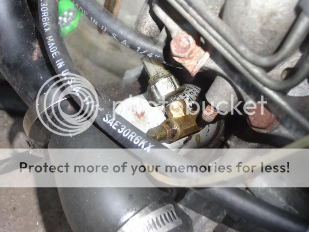
of interest so far i bought some fiitings and plumbed them so that i could run an aftermarket oil pressure gauge together with the oil pressure sensor. i could only find one configuration to fit it up and still be able to change the oil filter. ill post up some pics soon showing this and where the engine is now.
 
Been investigating and studying and i have some questions regarding the ecu-harness-control system:

  1. Does ecu switch to +12V to control components, or are the components live and ecu switches to ground?
  2. The scan port for the ecu is in the engine bay? The 6 socket female plug with 3 red wires, one pink, one black with white stripe and one black wire?
  3. The blue relay on the harness, left side engine bay is the fan relay? 1 green is for fuel pump and the other for supercharger? Just by the way, anyone know the amperage ratings for them off the back of their hand? If not I’ll check it this evening after work.
  4. 21: speed sensor- white/dark blue stripe. Where exactly does this wire take its signal from? speedo?
  5. Does original st have high temp warning signal that comes from ecu?
  6. There is a white wire with blue stripe that goes to position 34 in the ecu pin out. What’s that for?
  7. The solenoid over by the ufo is properly referred to as the vacuum control valve solenoid?
  8. Baz, you posted an image of the fuse layout, but for some reason I can’t open/see the image. Could you kindly repost it here?
 
1. Not sure
2. No scan port in the engine bay, there is one under the drivers side of the dash in mine, never used it though as the ecu has its own diagnostics.
3.One of the blue is for supercharger , one for the fan, one green is for fuel pump, not sure what the other is for.
4.Not sure
5.No not that I know of
6.Just looking at the pin out for the ecu. Nothing goes to pin 34 (you are probably reading incorrectly) , pin 33 is reverse lamp switch and 35 is power for control unit
7. I dont know, but pin 106 is vacuum tank solenoid
8. Cant find that image sorry
 
1. was hoping to find this out to know how to get the vacuum tank solenoid going.
2. will take some pics to identify the plugs i can't seem to figure out.
3. i only got 3 relays on the harness.
4. Ed said in some other thread that all nissan ecus have speed sensor input. i don't recall it being important but it would have been good to get it right.
5. ok.
6. the ecu pin out does not show a wire but my harness has one corresponding to that pin number.
7. i hope its the same thing.
8. ok.

I think i will have to leave the wiring to an experienced electrician. i have been told that wiring the engine is not difficult by an associate who did the ma10et swap. i would have liked to understand and know what's happening though.
 
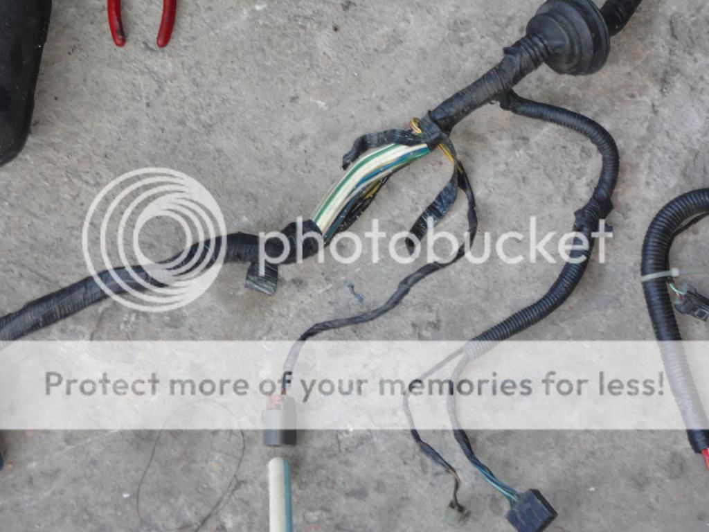
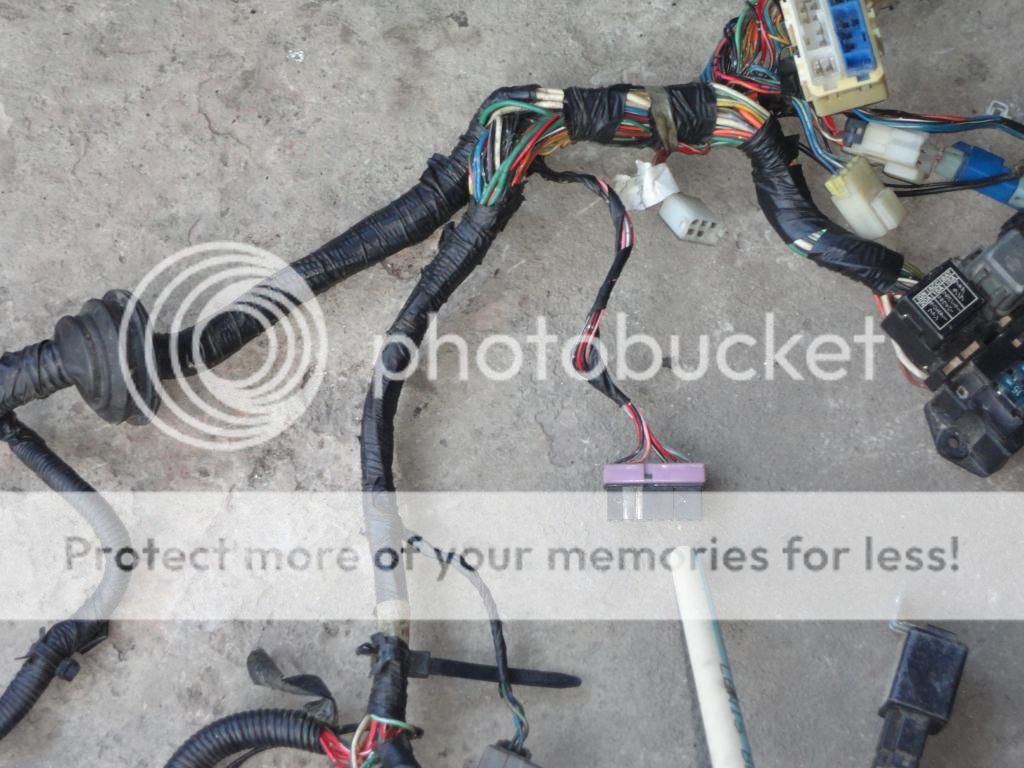
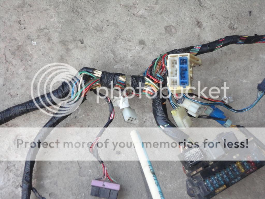
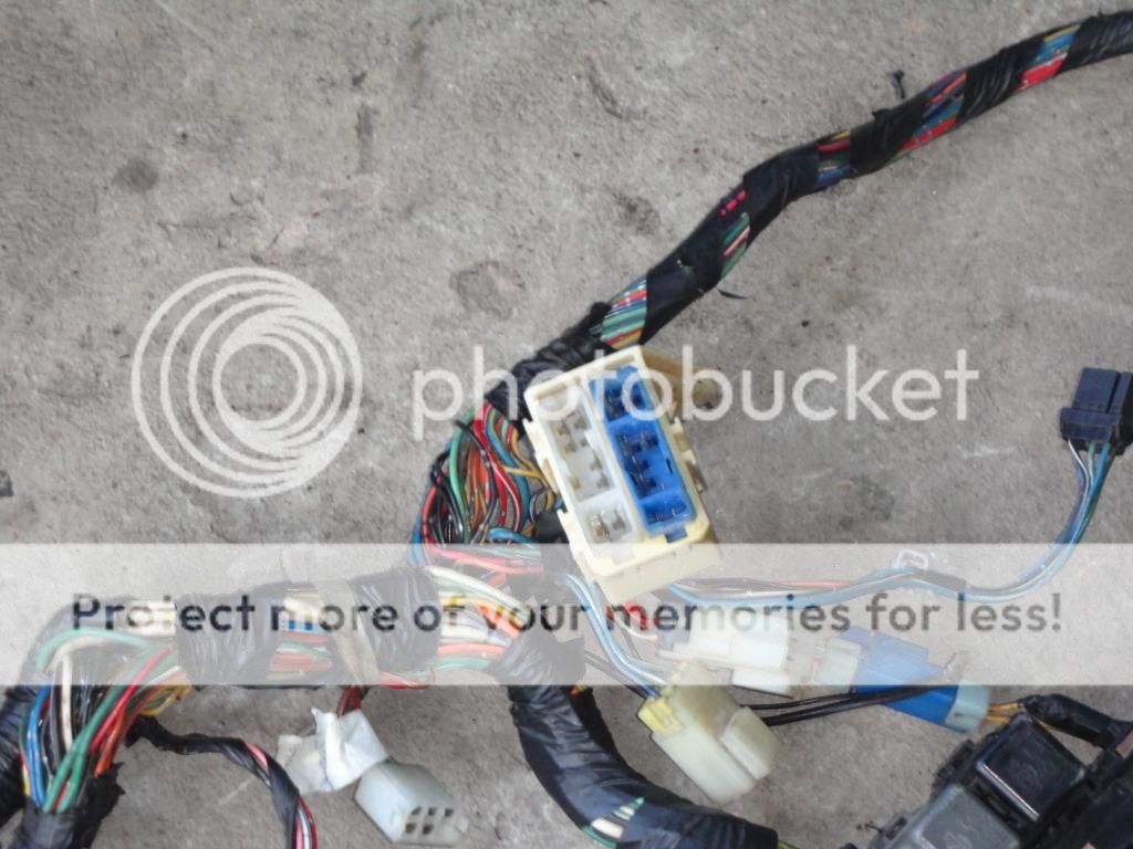
Nobody on here that I know of has done an Ma09ert swap so limited knowledge due to having original factory cars. No offense intended just if I cant answer your questions it because I dont know. Some high quality photos of the loom etc may help jog the memory. And you mate with the Ma10et swap, cant really compare the 2 as there is allot more wiring in the ma09.
Also 1 of the blue relays may be part of the cars loom not the engine loom
 
baz, logically i know that any electrician would have to figure the wires out before getting it to run right, that i could take the time to do it and that it would be best if i did it myself.

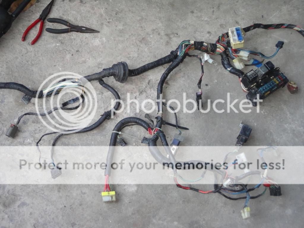
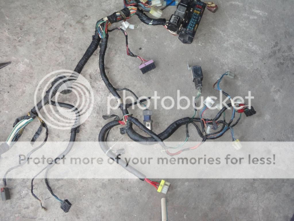
basically all jacks to the engine, coil, transistor and ecu are plugged in. i have no connection to the solenoid over by the ufo, i have two open jacks going over to the dash and a few open ones in the engine bay. to identify where the wires go to and from the ecu and relays would simply require lots of wire colour and continuity checks. but also important is not only where they go but what signal voltage runs in them and that question about whether the ecu switches to +ve voltage or switches to ground to activate solenoids, injectors, supercharger, relays etc is very important. i may have to do some in depth reading about nissan ecus to find out.

electrical makes my head hurt

i know that you are genuinely offering your best support baz. It is most appreciated.
i also know that a ma10et wiring is less sophisticated as well.

yes i got to get lots of pics up....later today.

respect
 
baz, i traced a few wires from the ecu to some jacks in this region of the st harness:


this is the jack for the solenoid over by the ufo:
DSC00714.jpg


i believe this one goes to the dials? sent u a pm about it.
DSC00715.jpg


i got one wire going to it but i don't know what this jack is for?:
DSC00716.jpg


i guess this is the scan port you told me about by the fuse box?
DSC00717.jpg


the wire for the headlight switch goes here so i assume its for the headlights?:
DSC00718.jpg


and just by the way, this is the fitting setup i have for the aftermarket oil pressure gauge:
DSC00723.jpg


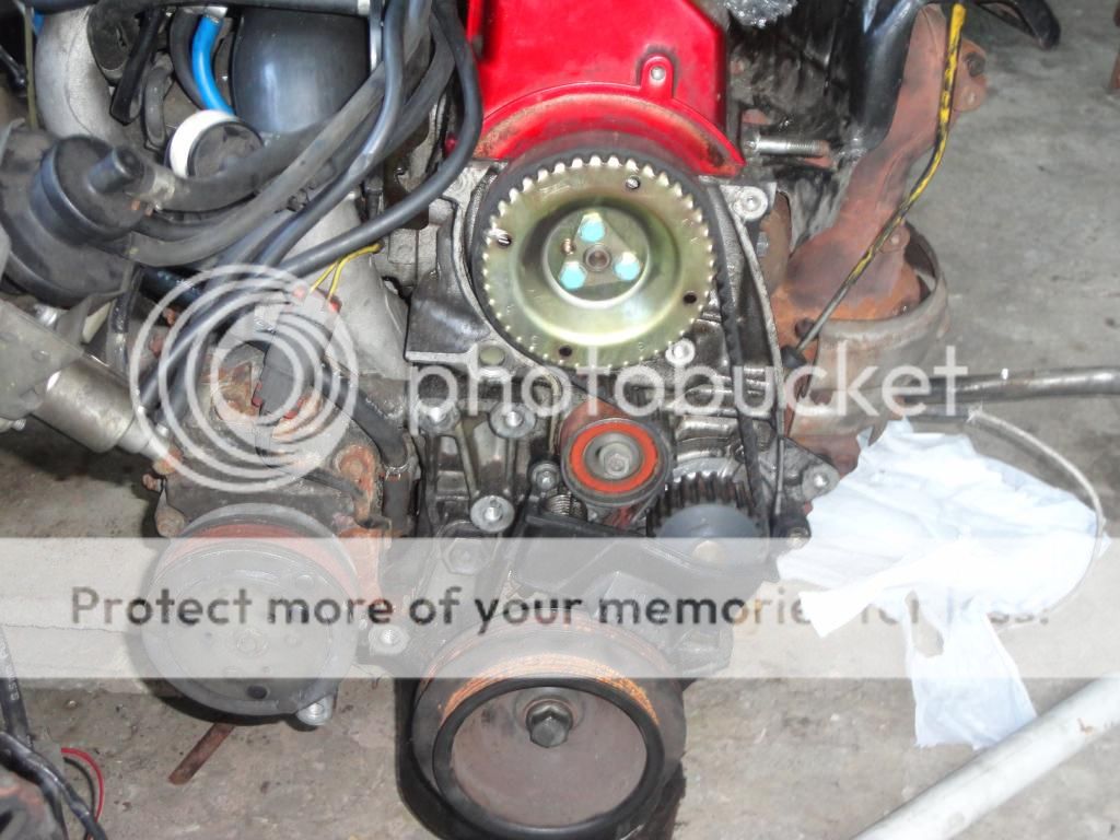
and i did this to my timing cover for easier inspection of pump, oil seal, tensioner and bearing and easy removal of belt without having to take down the troublesome engine mount:

DSC00724.jpg


slowly getting thru with wiring. will post up results when i am done.
 
okay baz. thanks for that. those wires run through the firewall, all the way around the engine bay, back to a 6 socket plug on the engine harness on the right side of firewall. i will not be using them.

i found this below the passenger seat in the car?
DSC00731.jpg


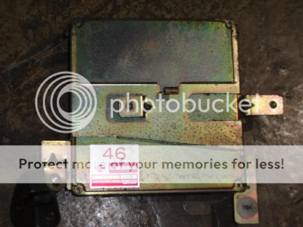
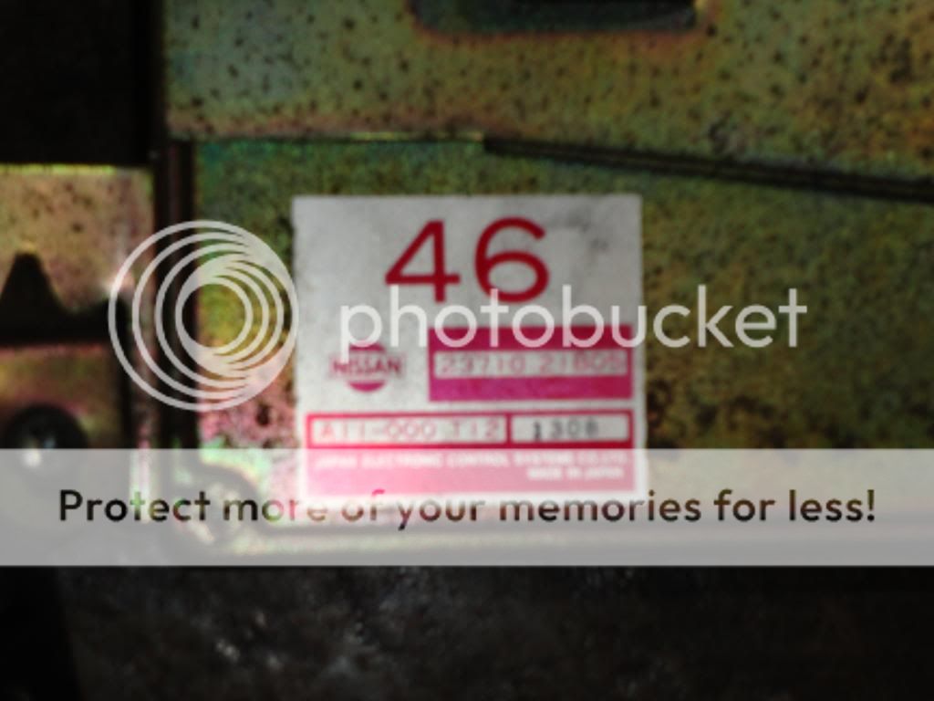
this is the ecu for the engine i am preparing. it seems original.
DSC00732.jpg

DSC00733.jpg


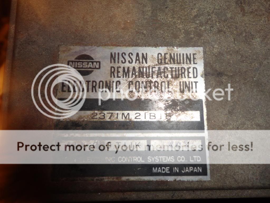
and this is for the other engine.it says remanufactured?
DSC00734.jpg

DSC00735.jpg


Can anyone shed some light on these items and the different numbers on them?

baz i checked the two engine harnesses. there are wires in both harnesses corresponding to number 34 on the ecu pin out diagram.

also the temp sensor goes to the dash directly but it also splits and sends a signal to number 5 on ecu pin out diagram.

also tester showed that 111, supercharger relay, and 25,key switch ignition signal are the same, and it also goes over to the solenoid by the ecu. therefore the solenoid is live and the ecu switches to ground through pin 113 to activate it. also, 110 which says injector no.2 i suspect is the ground for the supercharger that the ecu switches on and off to control it. it is the only way that the supercharger relay could not be on if it sees ignition +ve once the car is started. i will confirm today that 110 actually runs to the supercharger relay.

i think i figured out all the wires yesterday, and the ones for the engine to run right are truly only a few. diagrams promised when i confirm.

was wondering about the speed sensor. 1st if the car has the speed warning buzzer / beeper at approximately 110 km can i assume that it has a speed sensor in the speedo? i also read somewhere on this forum that when connected sometimes a lean condition occurs when at high speed? And disconnecting it solves / helps the problem? How important do you think it is for me to connect it?
 
When you are checking pins numbers are you looking from the the front of the connectors (ecu side) of the loom side (where the wires go into the plastic block connectors?
 
Never heard of a lean condition when the speed limit buzzer sounds? the buzzer is in the speedo clocks
 
checking from the front of the connector baz - ecu side. i must admit i did not check to see if the ecu has a corresponding pin to go into the 34 pin position, but there is definitely a wire going into the connector on both my harnesses.

somewhere here on the forum it was either frank or ed wrote about a leaning condition that occurs in 4th and 5th gear when the speed sensor signal is connected to the ecu? and that disconnecting it helped?

ed also wrote somewhere that the differences in operation of the car with the speed sensor connected or not would not be something noticeable?

oh and about the buzzer, i was wondering if i can expect to find a speed sensor in my speedo because it has the buzzer thing.

and baz, i need the quote on the vac tank. no luck locally.
the speed sensor trips a closed loop over-ride on the k11,s sleeper, which stops the acceleration enrichment over a certain speed, not sure if its the same on yours tho :)
 
thanks frank and welcome bro.
so its the k11.... my bad.

If i don't connect the speed sensor do you think the car should run ok?
 
good luck with the project mate :)
i had to leave it connected (when daily driving) when i was running my ghetto rising rate fuel reg, else it would acceleration enrich in top gear all the way up a long hill (which would probably destroy the cat) but the current nistune setup is,nt sensitive like that and i leave it disconnected now
 
frank you got me questioning again bro.

here we don't have MOT like you guys so i won't worry about the cat. in fact we take them out to improve flow.
got any air fuel ratios before and during acceleration enrichment?

also, would you think that if my speedo got the buzzer i would also find a speed sensor?

i am leaning towards checking for the speed sensor. if its there hook it up. if not well no. see how the car runs and decide how to go from there.

i will send you a pm. hopefully you can help me out.
 
i,ve only got narrowband mate, so i can only tell if its closed looping or off the scale rich or lean tbh, Ed did my nistune plug-n-play map (based on my SR20 topfeeds and stock maf)
 
Back
Top