Clocks, Dials, swop over.!

i have a nissan micra k11 1993 L.. iv just got hold of some clock with rev counter plug everything in and the rev counter doesnt work... can any body help so i can get this working..
as im thinking iv gotta run a wire to the dizzy cap. duno were to connect the wire help please even pictures thanks Jamie


helpp please....
 
I believe you can run a wire to the ecu but i'm not sure which wire it is, or you can get it from the dizzy, do a search there are a few threads on this already.
 
i have a nissan micra k11 1993 L.. iv just got hold of some clock with rev counter plug everything in and the rev counter doesnt work... can any body help so i can get this working..
as im thinking iv gotta run a wire to the dizzy cap. duno were to connect the wire help please even pictures thanks Jamie


helpp please....

let me guess, your car is 1.0l? in red maybe? lol, for some reason, nissan cut down on the loom on that one. i don't remember the fix off the top of my head but if you search it is on this site somewhere. you are better off picking up the signal from the ECU and taking it to the dials.
 
here you are, thats the wire you want. its the blue and black one.

attachment.php


if you dont have it in your loom, you will have to tap into the IGF (before the resistor) there is an inline resistor, i think you need to tap into the light green and black wire. the wire comes out of the ecu from pin number 3 (white and red) then there is the resistor and then it turns to light green and black. you want the light green and black side.
imo, loose wires in the engine bay look crappy.
 

Attachments

  • Tacho Dia Small.JPG
    Tacho Dia Small.JPG
    87.6 KB · Views: 7,330
let me guess, your car is 1.0l? in red maybe? lol, for some reason, nissan cut down on the loom on that one. i don't remember the fix off the top of my head but if you search it is on this site somewhere. you are better off picking up the signal from the ECU and taking it to the dials.

lol my car is a 1.0L but its white. and iv done a search found 1 its micra oli but i need to no where to solder the wire on the clocks.. Thanks

here you are, thats the wire you want. its the blue and black one.

attachment.php


if you dont have it in your loom, you will have to tap into the IGF (before the resistor) there is an inline resistor, i think you need to tap into the light green and black wire. the wire comes out of the ecu from pin number 3 (white and red) then there is the resistor and then it turns to light green and black. you want the light green and black side.
imo, loose wires in the engine bay look crappy.

to b onist no one see under the bonnet. and plus i dont fink my car has the spare plug.. Sorry to b a pain Jamie
 
same problem here i even have the wire running to the behind clocks but just need the right pin on the plugs going into the dials, :(
 
same problem here i even have the wire running to the behind clocks but just need the right pin on the plugs going into the dials, :(

lol we both stuck.. my car same as ur but myn white.. you no got ur rev counter working yet.. if i get myn to work to morro with out blowin ma ecu up. ill let you no.. Btw ow do u do a blog have you gotta b a member.
 
yer cheers matey, no you can do ablog look at the k11 section then blogs and post new thread.
i have my wire from the dizzy and i can feel the signal when the car is turned on its pulses so im sure there is enough signal coming through!
 
Pins

The missing wire in your loom needs to go from the ECU connector pin 2 to the new dials connector pin 2 - that's what is shown on my circuit diagrams and that's the only connection I would recommend.

If you're not sure which pin it this, this might help:

ECU end:

Pin 1 - has Red wire with Yellow tracer

Pin 3 - has White wire with Red tracer

Dials end:

Pin 1 - has Orange wire with Black tracer

Pin 3 - has Blue wire with Black tracer

FYI - the factory fit wire for the tacho is also Blue with Black tracer !


Good Luck !
 
If you guys want, I can see what lead goes into pin 2 on the clocks themselves tomorrow.

If any of you know, which pin is pin 2 on the clocks, that's the one for the tach. Should be a blue and black wire.

Edit: Graeme got there first whilst I was looking through the haynes and messing around with my spare dialset.
 
still no good iv found pin 2 on the ecu but...
be hind my clocks there 3 plugs.. which 1 is it some 1 please help picture would mean a lot thanks...
 
connect into the 2nd wire up in right connector as you look at clocks from behind.
Run this wire to your dizzy and connect it to the blue wire that comes out of or goes into top of dizzy this will be coverd by black plastic sleeving you cant miss it.
 

Attachments

  • clocks.JPG
    clocks.JPG
    9.7 KB · Views: 654
  • dizzy.JPG
    dizzy.JPG
    26.8 KB · Views: 795
cheers gonna give this a go

ok this still doesnt work i do believe its the correct places so could the signal not be strong enough coming from the dizzy any ideas?
 
If the wire is meant to be blue, with a black trace, then it goes into this pin, on the same socket

That's where the blue with black trace goes on mine anyway :confused:

Second one down on the right set, if you're looking at it.
 

Attachments

  • rev counter.JPG
    rev counter.JPG
    6.2 KB · Views: 708
I don't want you to break your clocks or anything, but it could be worth a shot, if there isn't another wire there.

Someone must know. You sure you've spliced into the right wire from the dizzy? Sure your connections are all good?
 
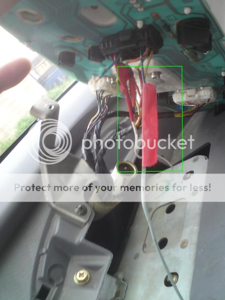
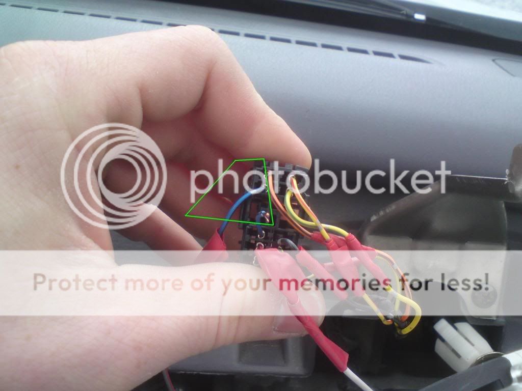
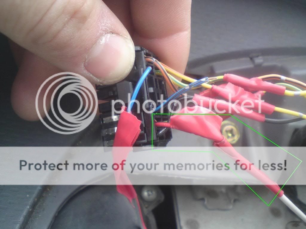
hi there, i think it is time at last for a picture of where i put the wire for clocks.
i spliced into a wire that came from the dizzy, check my blog, for the correct colour.
from the car that the tacho dials came from, i also cut the plug out, leaving about 50mm of wire, so that i could solder it on. the plug is the one directly behind the actual rev counter.
cut the plug out of your car, and then solder on the new one. all the colours are the same, so it is easy to match, but on the new plug that has been soldered in, there will be 2 spare wires, and it is one of these that you need to connect the dizzy wire too.
will get a pic in a min.....

right then, just had a look at the back of my clocks, the wire that you need to bring from the dizzy, needs to go to the blue and black wire, on the new plug.
also, i remembered, my old dials didnt have the clock on them, and the new ones did, and to get it to work, i bought a live 12v feed up to the clocks, and it goes to the red and black wire on the new plug.


hope this helps people.

here is the picture of the wire.....


DSC00260.jpg


here is another picture of the wire that you connect to on the new plug

DSC00261.jpg


here is the picture of the wire that i ran a 12v live to, so that the clock on the dash worked....

DSC00262.jpg
 
Time to hijack this thread rather than start another, :)

Is it possible to fit an 'after market' separate rev counter to a 94 L 1.0 Dot?

Funny you should ask, I was wondering the same thing.

Found some after market rev counters on ebay) which works out at 15GBP, but doesn't contain any fitting information.

I might just give it a try and see if it works.
 
If I'm not mistaken there are 3 wires going into an aftermarket rev counter, one goes to blue dizzy wire as shown here, one to 12v live and one to earth.
 
I'm currently trying to get my head around this tacho wiring up thing (hence the no sleep)

i think ive got it figured out right..

first off im going from the dizzy cause it seems easiest, i remove the cover over the wires, splice the blue wire and run a wire through to the back of my clocks (going into pin 2 on the plug)

and thats it?
 
Haha alright then cheers, will have a crack at that tomorrow if weather holds up, any particular wire i should buy?

bit of a noob with electrics
 
I've got everything to get my tacho working in theory, but i have that black and blue wire in pin 2 on the plug, can i splice into that wire and then take a new wire to the dizzy and splice there aswell?
 
thats a pre-facelift, machanical speedo drive (pre 98) like the pic i showed you, yours is a facelift model (electronic speedo)
 
Mine looks like this:

IMG_0353.JPG


And I need the wire positions from this thing ( I have no idea whats it called)

IMG_0357.JPG


If anyone can help me I will be more than thankful!
 
Right, going to have some freetime, maybe later today, but definately throughout the week,

1.0 T reg Equation facelift at your disposal,

I dont have much time so i need to know instructions of what you want me to do, i dont have to rip my car appart too much do i? (I have siezing screw phobia...and a party soon :p)

Mine has that clock in the image above, the exact same! (Y)
 
Excellent.

Well all you need to do is:

1. Unscrew the 2 screws. 1 from each side of the steering wheel.
2. Remove the plastic that is above the clocks, dials.
3. Unscrew 3 more screws. They are in a triangle shape.
4. Then behind of the dials you will see a harness. Remove the harness from the dials and you will see many wires attached to it.
5. There are 28 pins, 14 on each side with different wires on different ports. Some are free and not used. Just write down each wire that goes in a pin. Example. Pin 1 - Black, Pin 2 - Brown ect.

That is all that you have to do. It wont take more than 10 minutes and all you need is a screwdriver.

You can see the part and more pictures on this thread:

http://www.micra.org.uk/threads/40616-Harness-behind-the-dashboard-for-the-speedometer-fuel-level-ect-%28Help%29?p=422238#post422238

If you can do that you are THE BEST and I will be grateful

Thanks in advance
 
Yep, will get straight to it during the week, so are these instructions for the facelift micra? i think my steering wheel has airbag so i dont know if that changes anything.
 
Hey mate, been a busy few days, after the party i have a popped tire and then the spare tire randomly going flat haha, so i now have 4 new tires and some tracking issues sorted (Although nowi get some wheel vibration at high speed.....ANOTHER PROBLEM!) but heck, can sort that, i will begin looking into the clocks harness and try make a presentable diagram for you.

Thank you for your patience,

Migs ;).
 
Right so had a crack at it, instructions were spot on so good, very easy task but my problem is in the connector itself.

Kindly marked with VW and Audi simbol, the connector is fully closed (Atleast it is for a newb like me ^^)

20101026002.jpg


20101026003.jpg


20101026004.jpg


As you can see its closed off (Except that side part, but i dont wan't to mess with it until i'm 100% sure i can.)

On the bright side i did get to clean my dials :D.
 
Thanks alot for the effort but you missed the final step.

You should cut the white part that is tangled arround the wires and open the harness (the harness is consisted of two parts).

After you open the harness you will be able to see all the wires in different pins.

Example:

1 pin - black wire
2 pin - no idea
3 pin - no idea
----
28 pin - the final pin

There are two sides of the harness with 14 pins.

If you can do this it would be great, this way I am still stuck with my harness.

THANKS !
 
Hey mate, another day out so no progress,

I'm here really to ask about the harness, if i cut the tag, will the connector slide out of the harness or what? is there any risk of the wiring being pulled from the connector?

Its apserlutely essential that this vehicle does not break >< so i really want to be certain before dismantling this harness :).

Thanks for your patience, hopefully i will have the solutions to your problem soon yes!

Migs
 
Back
Top